DEVELOPMENT OF A THREE TON SOURCE OF COOL AIR
Problem
A remotely located office-shop building has been converted into a church. A one-ton air conditioner originally used to cool just the offices is the only system available for making the entire building comfortable for a few hours on Sunday mornings. It is believed that finances do not permit the purchase and installation of an additional unit or units. It has been determined that 3 tons of cooling are required on Sundays to accommodate the current level.
It has been suggested that the air conditioner be made to run all week to form a huge block of ice or to cool some other “storage” facility. Then on Sunday mornings, air can be moved past the ice and the cooled air used to make the occupants comfortable.
It is desired to design an appropriate “storage” facility using minimum space that can later be used to provide cool air. Ice is not necessarily the answer, although water is inexpensive.
To be designed, selected, or determined:
1. A facility (liquid, gas, solid) that can be cooled during a 6 ½ day period by one-ton air conditioner to yield 3 tons of cooling for half a day.
2. Dimensions of the required facility (should be as small as possible).
3. Total cost of the facility (assuming space within the building is available). Cost should include all items required, including insulation, if any, and operation of the one-ton unit.
4. Compare these costs to those associated with the purchase of the proper-size cooling system (including installation and operation).
5. Make a recommendation based on your calculations.
1. Introduction
It is important to understand how and why the problem statement was planted in order to start searching for solutions and chose the most adequate. Now, just by reading the project description it is noticeable that budget is the most important parameter followed by trying to manage building the system in the minimum space possible. For this reasons it is imperative to research electricity, air conditioner and other system demand prices as well as the physical parameter of such systems to select the best option.
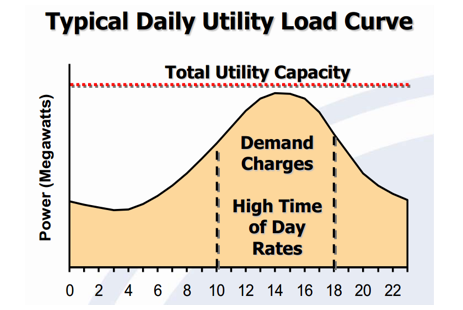
Being the most important parameter the cost of the project, then the first thing researched were electricity rates. Electricity has off-peak and on-peak periods; during off-peak the cost of the power is relatively low because the system demand for power is low, off-peak hours are during the night because it is the time of the day with less power demand. In the other hand, on-peak hours is the time of the day when the cost of the power is high because of the high demand, one peak hours are usually during regular office/working hours during the day.
Being the most important parameter the cost of the project, then the first thing researched were electricity rates. Electricity has off-peak and on-peak periods; during off-peak the cost of the power is relatively low because the system demand for power is low, off-peak hours are during the night because it is the time of the day with less power demand. In the other hand, on-peak hours is the time of the day when the cost of the power is high because of the high demand, one peak hours are usually during regular office/working hours during the day.
An important parameter dealing with price is the operating cost of the devices used in the system. For this reason, it is critical to engineer the way to choose the most efficient system in order to reduce cost. This is done through analysis to verify the functionality of the materials or devices such as pumps or chillers.
The next important parameter is the limited space to install new hardware. Because of this it is crucial to find the least room option to fix the problem. Through the available solutions the smallest one has to be chosen and designed to build the less space system possible.
To summarize, the project’s design has to be relatively economical work efficiently and occupy the least space possible to meet the requirements of the issues stated above. At the end, the prices of purchasing a three ton air conditioner and its operating hours will be compared in short and long term to the solution selected to approach the problem.
Ice Thermal Energy Storage
Because of the previous parameters, the approach for the problem that the team chose was to utilize thermal energy storage in the form of ice. Energy storage basically works by adding to the existing air conditioner system additional hardware which will store energy during off-peak hours to be used during on-peak hours to reduce the electricity demand the following day. The energy stored is ice or water based because of its easy manageability, properties and cost.
However, there are different system types of thermal energy storage, dynamic systems and static systems. The dynamic systems require more refrigeration and they can produce lower temperature chilled water, which enables smaller pumps, piping and coils. These systems are usually used in large buildings such as commercial centers. In the other hand, Static systems are more compact, simpler and less costly. As a result, static systems are more common and popular than dynamic systems. After reviewing the characteristics of each system, the static one will be the one used.
The system works in the following way:
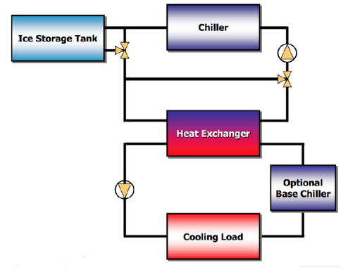
The conventional air conditioner system has a water chiller of its own to cool the air retrieved from the surroundings. This chiller cools water which is then used in a heat exchanger to cool the incoming air. The only hardware added to the A/C system for the Thermal Energy Storage system to work is copper coils where glycol will be circulating. These coils lead to the storage tank, which will cool the glycol.
There are two different modes for the thermal energy storage system; charge and discharge. The charging mode is when the energy is being stored into the tank, which is during off-peak hours. Energy is stored in a tank in the form of ice by circulating glycol through copper coils inside the storage tank which is filled with water. Glycol circulates through those coils and comes outside to enter a chiller which will cool the glycol to the desired temperature. The cycle continues until the water in the tank is transformed into ice. In summary, cold glycol enters the Tank, cools the water inside the tank, then warm glycol comes out the tank where it is cooled again with the help of the chiller.
Conversely, the discharge mode of the Thermal storage system takes the glycol to the A/C unit where it enters to copper coils added to the A/C unit. The outside air which is the one desired to cool will pass through these coils containing the cool glycol, which will cool the air to the desired level depending on the coils. After this, warm glycol will come out the A/C system and it will enter the storage tank to be cooled again. This cycle will continue until the ice in the storage tank depletes.
The following diagram symbolizes the system.
The next important parameter is the limited space to install new hardware. Because of this it is crucial to find the least room option to fix the problem. Through the available solutions the smallest one has to be chosen and designed to build the less space system possible.
To summarize, the project’s design has to be relatively economical work efficiently and occupy the least space possible to meet the requirements of the issues stated above. At the end, the prices of purchasing a three ton air conditioner and its operating hours will be compared in short and long term to the solution selected to approach the problem.
Ice Thermal Energy Storage
Because of the previous parameters, the approach for the problem that the team chose was to utilize thermal energy storage in the form of ice. Energy storage basically works by adding to the existing air conditioner system additional hardware which will store energy during off-peak hours to be used during on-peak hours to reduce the electricity demand the following day. The energy stored is ice or water based because of its easy manageability, properties and cost.
However, there are different system types of thermal energy storage, dynamic systems and static systems. The dynamic systems require more refrigeration and they can produce lower temperature chilled water, which enables smaller pumps, piping and coils. These systems are usually used in large buildings such as commercial centers. In the other hand, Static systems are more compact, simpler and less costly. As a result, static systems are more common and popular than dynamic systems. After reviewing the characteristics of each system, the static one will be the one used.
The system works in the following way:
The conventional air conditioner system has a water chiller of its own to cool the air retrieved from the surroundings. This chiller cools water which is then used in a heat exchanger to cool the incoming air. The only hardware added to the A/C system for the Thermal Energy Storage system to work is copper coils where glycol will be circulating. These coils lead to the storage tank, which will cool the glycol.
There are two different modes for the thermal energy storage system; charge and discharge. The charging mode is when the energy is being stored into the tank, which is during off-peak hours. Energy is stored in a tank in the form of ice by circulating glycol through copper coils inside the storage tank which is filled with water. Glycol circulates through those coils and comes outside to enter a chiller which will cool the glycol to the desired temperature. The cycle continues until the water in the tank is transformed into ice. In summary, cold glycol enters the Tank, cools the water inside the tank, then warm glycol comes out the tank where it is cooled again with the help of the chiller.
Conversely, the discharge mode of the Thermal storage system takes the glycol to the A/C unit where it enters to copper coils added to the A/C unit. The outside air which is the one desired to cool will pass through these coils containing the cool glycol, which will cool the air to the desired level depending on the coils. After this, warm glycol will come out the A/C system and it will enter the storage tank to be cooled again. This cycle will continue until the ice in the storage tank depletes.
The following diagram symbolizes the system.
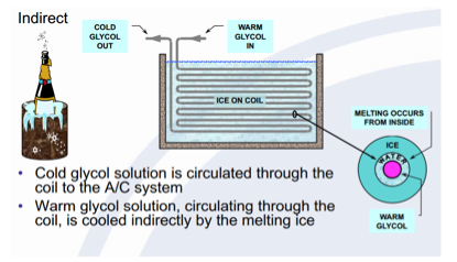
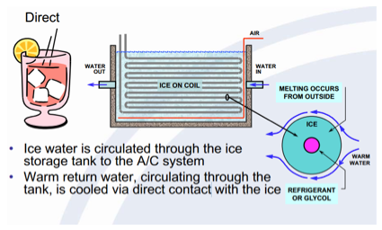
Furthermore, there are two basic types of static systems for thermal energy storage; Internal Melt and External Melt. The Internal melt system works by circulating cold glycol (refrigerant) through a storage tank and coils added to the A/C system. Conversely, the External melt system works by circulating the iced water through the storage tank and coils added to the A/C system.
The Internal Melting system is also known as indirect contact.
The Internal Melting system is also known as indirect contact.
The External Melting system is known as direct contact.
Even though, both systems work efficiently, here are some general characteristics to evaluate both of the systems in order to choose the best option for the problem at hand.
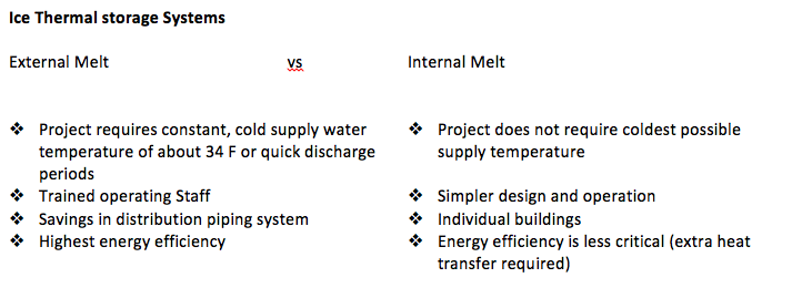
The system chosen to solve the problem is the Internal Melt, being the first reason because it is commonly used for individual buildings and the obvious financial advantage. After opting for the best solution, the next step is to engineer de way into a clever design, which will deliver the required amount of energy with some tolerance. The major challenges for this project are the several iterations in order to converge the closest to an ideal solution.
Energy
It is important to understand what a “ton “of energy is before designing a system which will deliver three tons of cooling for half a day (twelve hours). Here are a couple of definitions, which will help understand more about energy storage.
A ton of energy contains approximately 12,000 BTU’s or 12660.67 KJ of energy.
A ton-hour is the capacity of tons times the number of hours.
Now, the problem states that three tons of cooling is required for half a day, which sums up to 36 tons of air (432000 BTU’s) for all the twelve hours of operation. Because of this, the design of the tank has to be large enough to store 36 tons of energy which will be spent throughout all the twelve hours by using three tons per hour. It is important to note that the space at the building is limited; therefore the tank and its components have to be designed to occupy the least space.
Design Plan
Since this is a complete iteration process problem the easiest way to progress is by constructing an excel database and calculator. The way to create this is first by typing all the material and substance properties which are contemplated to generate the design. After completing a solid database, the next step is to define the inputs and outputs for the iterations, by doing so; one can easily manage to change anything without compromising the whole problem structure. One the inputs and outputs are carefully chosen, the following step is to start producing the calculations by inserting formulas into the excel sheets using the existing databases.
· The excel file is located at the end of this report in order for the reader to get a better understanding of the calculator.
The analysis was separated in pieces in order to make it easier to create the calculations. The objects analyzed were the Water tank, the A/C unit and the pump selection, the chiller selection, the minor loses and the insulation materials.
The following is the data base is the properties of the substances used in the Water tank to be analyzed:
First, the properties of water at zero degrees Celsius, which in other words is pure ice. These properties are needed in order to view how ice behaves during the cycle.
Properties of Water at 0
Latent heat of Fusion of water 333.7 KJ/Kg
Density of ice 917 Kg/m^3
Pr of water at 0 13.5
B volume expansion water at 0 -0.000068 1/k
Dynamic viscosity at 0 0.001792 kg/m*s
Thermal conductivity at 0 0.561 w/m*k
The second thing considered where the properties of water at other temperatures according to what were needed in the calculations. The following are properties from 0 to 25 degrees Celsius.
Properties of water from 25 to 0
Cp of water ranging from 0 to 26.66 C 4.2 KJ/KgK
Pr of water @ 10 9.45
B volume expansion @ 10 0.000733 1/k
Dynamic viscosity @ 10 0.001307 kg/m*s
Thermal conductivity @ 10 0.58 w/m*k
Pr of water @ 15 8.09
B volume of expansion @ 15 0.000138 1/k
Dynamic viscosity @ 15 0.001138 kg/m*s
Thermal conductivity @ 15 0.589 w/m*k
Pr of water @ 5 11.2
B volume expansion @ 5 0.000015 1/k
Dynamic viscosity @ 5 0.001519 kg/m*s
Thermal conductivity @ 5 0.571 w/m*k
Pr of water @ 0 13.5
B volume expansion @ 0 -0.000068 1/k
Dynamic viscosity @ 0 0.001792 kg/m*s
Thermal conductivity @ 0 0.561 w/m*k
The refrigerant which will be used in the system will be ethylene glycol because it is the most common one in these types of systems. The following properties are for ethylene glycol (the refrigerant).
Properties of Glycol
Cp of Ethyene Glycol 2294 J/KgK
Density of glycol room temp 1109 kg/m^3
Dynamic Viscosity 0.021329 kg/m s
Pr of Glycol 615
Thermal conductivity 0.242 w/m*k
Air properties at room temperature are the last properties used in this system. Air is used in the A/C system, therefore the properties are necessary.
Properties of air
Density of air 1.204 kg/m^3
Pr 0.7309
Kinematic Viscocity 0.00001516 m^2/s
Thermal conductivity 0.02514 w/m*K
Cp 1007 J/kg*K
Now that the data base is established, the next step is to work the way to the solutions. The first step to process the calculations is to decide what the inputs and outputs of the problem solution will be. Once these are clear, the calculator iterations may be computed. The following table contains what the data is known so far which will not change through the entire process:
3 tons of energy 10543.5 Watts
Require Usage Time 12 hr
Required stored energy 455784.192 KJ
Storage Tank Water Initial Temperature 20 C
Specific Heat of Water 4.2 KJ/kgK
Required Heat Transfer to cool the water from 20 to 0 degrees celcius 114731.41 KJ
Required Mass of Ice 1365.85 Kg
Volume of ice 1.49 m^3
Required energy to convert water to ice @ 0 degrees celcius 455784.19 KJ
Total heat transfer to transform water to ice starting at 20 degrees celcius 570515.60 KJ
Maximum Time available for freezing the whole volume of ice 156 hrs
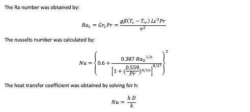
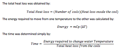
The required heat transfer to cool the water from 20 to 0 degrees was calculated with the following equation:
Q ̇=h A ∆Tlm=m ̇Cp (Te-Ti)
The required mass of the ice was calculated with the next equation:
m= (Energy Stored)/(Latent heat of fusion)
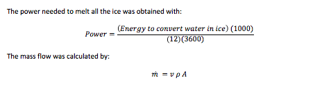
The required energy to convert water into ice (water to zero degrees Celsius) was obtained by:
Energy=(Mass of ice)(Latent heat of Fusion)
The rest of the data is self explanatory and requires easy calculations.
As stated above the following step is to decide what the inputs and outputs are going to be. The values on the table are the final values after the numerous iterations done in the excel calculator, in order to obtain the optimum parameters. It is important to note that these calculations were made in an ideal world (assuming perfect conditions). The outcome of the input values is the following:
*Note, separation is a term used for when the initial pipe is separated into several smaller pipes.
The next table is simple information which was obtained with the input values, which will also help do further calculations. It is important to note that all the tables coming from this point on will all be functions of the first table, which is the input table.
Latent heat of Fusion of water 333.7 KJ/Kg
Density of ice 917 Kg/m^3
Pr of water at 0 13.5
B volume expansion water at 0 -0.000068 1/k
Dynamic viscosity at 0 0.001792 kg/m*s
Thermal conductivity at 0 0.561 w/m*k
The second thing considered where the properties of water at other temperatures according to what were needed in the calculations. The following are properties from 0 to 25 degrees Celsius.
Properties of water from 25 to 0
Cp of water ranging from 0 to 26.66 C 4.2 KJ/KgK
Pr of water @ 10 9.45
B volume expansion @ 10 0.000733 1/k
Dynamic viscosity @ 10 0.001307 kg/m*s
Thermal conductivity @ 10 0.58 w/m*k
Pr of water @ 15 8.09
B volume of expansion @ 15 0.000138 1/k
Dynamic viscosity @ 15 0.001138 kg/m*s
Thermal conductivity @ 15 0.589 w/m*k
Pr of water @ 5 11.2
B volume expansion @ 5 0.000015 1/k
Dynamic viscosity @ 5 0.001519 kg/m*s
Thermal conductivity @ 5 0.571 w/m*k
Pr of water @ 0 13.5
B volume expansion @ 0 -0.000068 1/k
Dynamic viscosity @ 0 0.001792 kg/m*s
Thermal conductivity @ 0 0.561 w/m*k
The refrigerant which will be used in the system will be ethylene glycol because it is the most common one in these types of systems. The following properties are for ethylene glycol (the refrigerant).
Properties of Glycol
Cp of Ethyene Glycol 2294 J/KgK
Density of glycol room temp 1109 kg/m^3
Dynamic Viscosity 0.021329 kg/m s
Pr of Glycol 615
Thermal conductivity 0.242 w/m*k
Air properties at room temperature are the last properties used in this system. Air is used in the A/C system, therefore the properties are necessary.
Properties of air
Density of air 1.204 kg/m^3
Pr 0.7309
Kinematic Viscocity 0.00001516 m^2/s
Thermal conductivity 0.02514 w/m*K
Cp 1007 J/kg*K
Now that the data base is established, the next step is to work the way to the solutions. The first step to process the calculations is to decide what the inputs and outputs of the problem solution will be. Once these are clear, the calculator iterations may be computed. The following table contains what the data is known so far which will not change through the entire process:
3 tons of energy 10543.5 Watts
Require Usage Time 12 hr
Required stored energy 455784.192 KJ
Storage Tank Water Initial Temperature 20 C
Specific Heat of Water 4.2 KJ/kgK
Required Heat Transfer to cool the water from 20 to 0 degrees celcius 114731.41 KJ
Required Mass of Ice 1365.85 Kg
Volume of ice 1.49 m^3
Required energy to convert water to ice @ 0 degrees celcius 455784.19 KJ
Total heat transfer to transform water to ice starting at 20 degrees celcius 570515.60 KJ
Maximum Time available for freezing the whole volume of ice 156 hrs
The required heat transfer to cool the water from 20 to 0 degrees was calculated with the following equation:
Q ̇=h A ∆Tlm=m ̇Cp (Te-Ti)
The required mass of the ice was calculated with the next equation:
m= (Energy Stored)/(Latent heat of fusion)
The required energy to convert water into ice (water to zero degrees Celsius) was obtained by:
Energy=(Mass of ice)(Latent heat of Fusion)
The rest of the data is self explanatory and requires easy calculations.
As stated above the following step is to decide what the inputs and outputs are going to be. The values on the table are the final values after the numerous iterations done in the excel calculator, in order to obtain the optimum parameters. It is important to note that these calculations were made in an ideal world (assuming perfect conditions). The outcome of the input values is the following:
*Note, separation is a term used for when the initial pipe is separated into several smaller pipes.
The next table is simple information which was obtained with the input values, which will also help do further calculations. It is important to note that all the tables coming from this point on will all be functions of the first table, which is the input table.
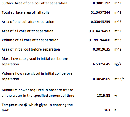
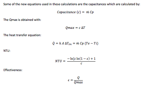
The surface area of one coil after separation was calculated by:
Surface Area= πDL
The mass flow rate before separation was obtained by:
(m ) ̇=v ρ A
The minimum power required to freeze the water in a specified amount of time:
Power= ((Total heat transfer)⁄(Avaliable time))/(3600 (to convert h to s)) (1000)
The following table contains the parameters for the small pipes which are the ones who come after separation. The volume flow rate for each of these pipes is the same because it was assumed that the flow would divide itself equally in each pipe. For this reason several data comes out to be the same.
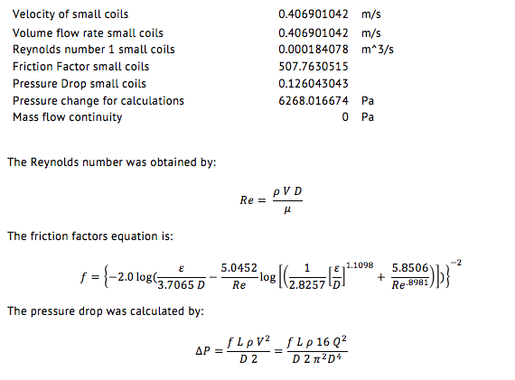
The next tables are the calculations to obtain the heat transfer coefficient on each of the desired states. There could be infinitely more states, however there were only four stats chosen to demonstrate the behavior of the tank as time passes and the refrigerant cools the water inside the tank.
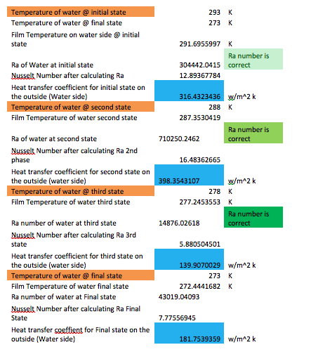
The following table contains the overall heat transfer coefficient for each of the cases as well as other information obtained in the inside coils.
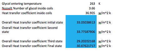
The equation used to obtain the overall heat transfer coefficient in each of the cases was the following:
U = 1/(1/h+ 1/h)
The following table is a comparison for all the states in terms of temperatures and heat losses. It is pretty self explanatory. Moreover, the temperature of the surfaces was iterated so that the heat loss comparison ended in zero.
U = 1/(1/h+ 1/h)
The following table is a comparison for all the states in terms of temperatures and heat losses. It is pretty self explanatory. Moreover, the temperature of the surfaces was iterated so that the heat loss comparison ended in zero.
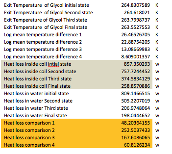
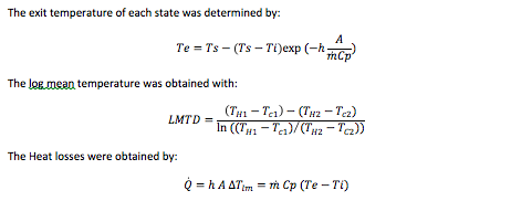
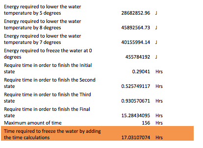
The next table contains the total heat losses, the required energy to move the water from one state to the next and the time it takes to do so. As it can be observed the total time for the water to completely transform into ice reached 17 hours. Although this number may change by alternating the inputs, seventeen hours were chosen because of the electric power demand. This is the last table which has to do with the water tank analysis.
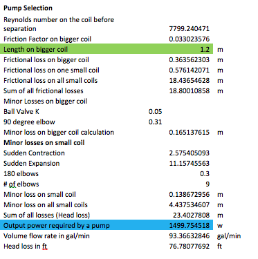
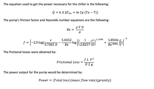
The following excel calculations are for other components of the system. As stated above, a chiller will be the device used to cool down the refrigerant once it enters the water tank. In order to choose the correct chiller one must know what the total power required to lower the temperature of the refrigerant as desired has to be. Other important devices which are indispensable in the cycle are the pumps which will be controlling the flow of the glycol. There will be two pumps the charging pump and the discharge pump, one to control the flow in the water tank and the other one to control the flow in the A/C unit respectively. In order to select the proper pumps one must know the required power and flow rate of the refrigerant in the system.
The calculations for the power of both the charging pump and the chiller were done in excel due to the several iterations needed in order to achieve a logic solution. The following table contains the values for each of the parameters calculated to find the power for each of the devices:
The calculations for the power of both the charging pump and the chiller were done in excel due to the several iterations needed in order to achieve a logic solution. The following table contains the values for each of the parameters calculated to find the power for each of the devices:
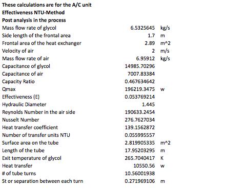
The following calculations are done in the discharging mode of the system, in other words what happens inside the A/C unit with the new added coils where refrigerant circulates and cools air. The first table has input values which will be used for iterations in order to achieve the most efficient result for the coil design inside the A/C unit.

The next table contains the analysis in the A/C unit, which was done with the NTU-Method. This method allows the user to calculate the analysis values with less iterating than in the previous analysis. For this reason, it is believed that the results obtained in these calculations have less error.
The following step is to calculate the second pump, which is the discharge pump. This pump is the one driving the glycol into the air conditioner unit. This is similarly done as in the first pump, which is the charge pump. Another important analysis is the minor loses due to the small components in the system design. The following table contains the minor losses and the second pump:
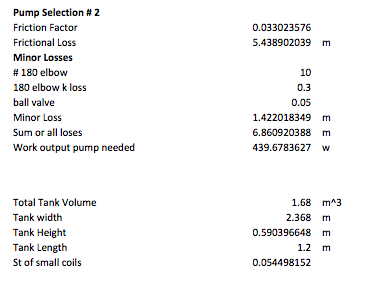
All the calculations are pretty straight forward; the majority of these operations have to do with the K constant for each of the components introduced in the system. However, the final table contains the analysis for the insulation for the tank. The insulation is important to verify what kind of protection it is better to reduce the losses of the system to the surroundings.
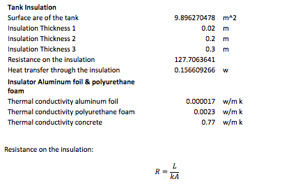
The insulators used were aluminum foil and polyurethane foam, because they have the lowest thermal conductivity among all the materials in the insulator charts. It is imperative to have the best insulator because the project relies on thermal storage.
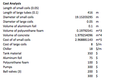
The last calculations done for this project were for the prices of the materials and the operating cost of the devices. However, the prices listed in the table below are estimates because real prices could not be found exactly as needed. For this reason some of the prices are closed numbers to make the calculations easier. These estimates were decided by basing them in online prices found for each material and devices. The table below contains input values for the prices:
The last calculations done for this project were for the prices of the materials and the operating cost of the devices. However, the prices listed in the table below are estimates because real prices could not be found exactly as needed. For this reason some of the prices are closed numbers to make the calculations easier. These estimates were decided by basing them in online prices found for each material and devices. The table below contains input values for the prices:
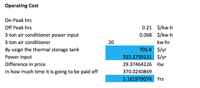
The following table contains the operating prices for the devices used in the system.
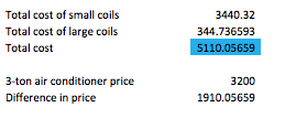
Finally this last table has the total cost of everything contemplated in price
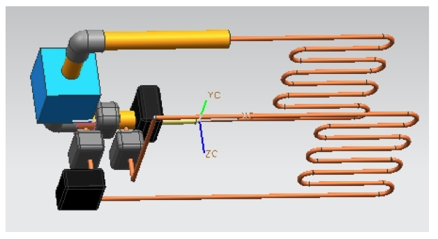
CAD Design
The next Cad is a representation in Unigraphics software NX for the design of the system of the ice thermal storage. The cad design contains the representation of the major components, the coils, pipes, pumps, valves and chiller. The copper color pipes represent the coils, the black boxes the pumps, the blue box the chiller, the valves are the gray boxes and the rest is tubing. Now, the first coil which is connected to a pump and a valve is the coil which is inside the A/C system. The other coil represents the one inside the water tank. Even though this design is only representative, it gives a clear idea of the path that the refrigerant will take in the system, which is helpful to visualize how it works.
Conclusion
In summary, the problem asked for a design that would improve a one-ton air conditioner to a three tons air conditioner. The first step consisted in the design of a thermal energy storage device. Such design would be in charge of storing thermal energy in the form of a block of ice. The second step consisted in designing another particular unit for transferring the energy stored. This second unit is the air conditioner unit, which is in charge of distributing that energy previously stored. In other words, it will decrease the hot temperature inside the church by transferring the heat to the cool source (block of ice).
Algorithm for calculations
| thermal_system_calculator_autosaved_1.xlsm |
