OPERATIONAL PROCEDURE FOR IMPROVING SAFETY HAZARDS OF A LASER IGNITION SETUP
The purpose of this document is to provide description and operation procedures for the laser ignition setup, to analyze hazards and existing safety measures, and to give recommendations for improving safety of the setup.
1. Description of the setup
1.1 Purpose and main components of the setup
The laser ignition setup has been constructed for experiments with combustible gas-generating mixtures. The purpose of these experiments is to investigate combustion characteristics and mechanisms of the mixtures as well as to analyze the released gases. Examples of the studied mixtures include:
· sodium chlorate with various additives for oxygen generation
· ammonia borane with various additives for hydrogen generation
The setup should NOT be used for experiments with mixtures that may exhibit detonation. Before starting experiments with a new system, the maximum amount of the sample should be determined following the procedure described in the Appendix 1.
Figure 1 shows main components of the setup: a windowed chamber (volume: 11.35 L), a CO2 laser (Synrad Firestar ti-60), a pressure transducer (Omegadyne PX409-030AI), a mass-spectrometer (Pfeiffer Omnistar GSD 320), an infrared video camera (FLIR SC7650E), and a high-resolution video camera (Sony XCD-SX90CR).
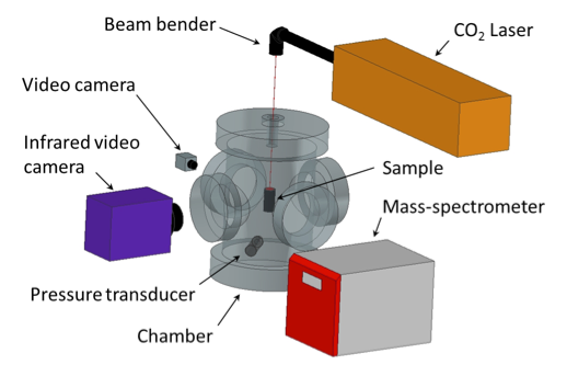
Fig 1. Main components of the laser ignition setup
The setup includes three computers (Figs. 2 and 3):
· Computer 1 controls the pressure transducer and the laser.
· Computer 2 controls the two cameras.
· Computer 3 controls the mass-spectrometer.
· Computer 1 controls the pressure transducer and the laser.
· Computer 2 controls the two cameras.
· Computer 3 controls the mass-spectrometer.
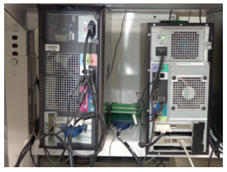
Fig. 2. Computers 1 (left) and 2 (right).
|
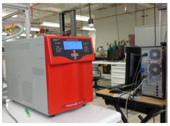
Fig. 3. Mass-spectrometer and computer 3.
|
Before the experiment, the sample is installed on a special holder and an inert gas (argon) environment at 1 atm absolute pressure is created inside the chamber. The sample can be either a compacted powder pellet or the tested mixture in any state (e.g., loose powder, paste, and gel) located in a quartz glass tube. Note that in the latter case use of the infrared camera is impossible unless the tube is made of sapphire or some other material that is transparent for infrared radiation recorded by the camera. Two different sample holders – for pellets and for gels/pastes – are used in this setup (Fig. 4).
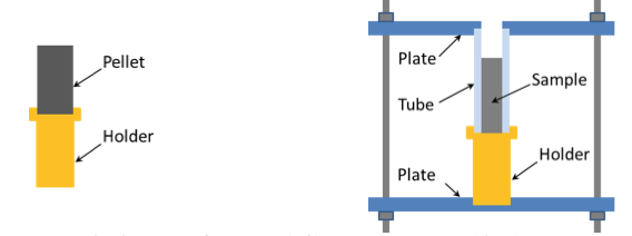
Fig. 4. Holders for pellets (left) and gels or pastes (right).
During the experiment, the laser beam of preset power and pulse duration enters the chamber and heats the sample at the top. If the energy transferred to the sample is sufficient, the ignition occurs and the combustion wave propagates downward over the sample. The “normal” video camera serves for observations before and during combustion as well as for the front velocity measurements from video records. The infrared camera is used for temperature mapping of the burning sample. The pressure transducer measures pressure during all operations and records pressure during the experiment. After the combustion, the gas environment in the chamber is analyzed using the mass-spectrometer.
1.2 Chamber gas and filling/evacuation system
The chamber was fabricated by A&N Corporation. The body (cylinder with flat ends) is made of stainless steel. The chamber is equipped with three window ports and a window door port on a lateral surface (Fig. 5). One window (Fig.6) is made of sapphire (for infrared video recording), while other three windows on the lateral surface are made of borosilicate glass. A zinc selenide (ZnSe) window is installed on the chamber lid (Fig. 7) for the introduction of a laser beam into the chamber. The pressure transducer is connected to the chamber (Fig. 8). The chamber is equipped with an 8-wire feedthrough, which could be used for thermocouple measurements (see Fig. 6).
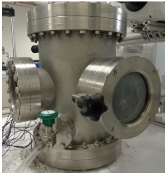
Fig. 5. Chamber. View from the window door port side.
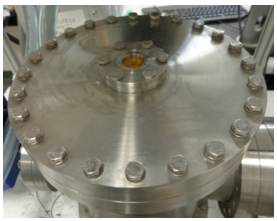
Fig. 7. Lid with Zn-Se window.
|
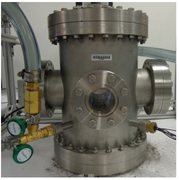
Fig. 6. Chamber. View from the sapphire window port side.
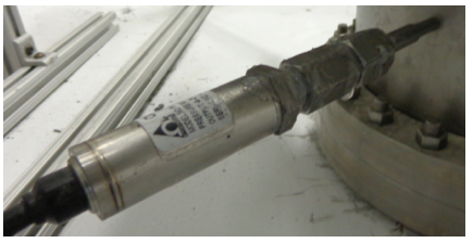
Fig. 8. Pressure transducer.
|
The chamber has been designed for working pressure of 1 atm or less. The chamber has been tested for high vacuum by the manufacturer.
Figure 9 shows a schematic diagram of the gas filling/evacuation system, which includes the pressure transducer, a vacuum pump (Fisher Scientific Maxima C Plus), a compressed argon cylinder, a pressure regulator, six valves, and PVC tubing. Valves 1-3 are precise needle valves, while 4-6 are ball valves. Valve 6 serves for connecting the vacuum pump to either this or another setup. Figures 10-13 show photographs of the valves and vacuum pump. The chamber is located under the inlet of the vent (Fig. 14).
Figure 9 shows a schematic diagram of the gas filling/evacuation system, which includes the pressure transducer, a vacuum pump (Fisher Scientific Maxima C Plus), a compressed argon cylinder, a pressure regulator, six valves, and PVC tubing. Valves 1-3 are precise needle valves, while 4-6 are ball valves. Valve 6 serves for connecting the vacuum pump to either this or another setup. Figures 10-13 show photographs of the valves and vacuum pump. The chamber is located under the inlet of the vent (Fig. 14).
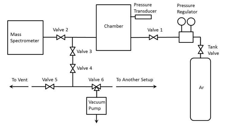
Fig. 9. Schematic of the gas filling/evacuation system.
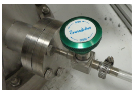
Fig. 10. Valve 1.
|
|
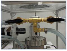
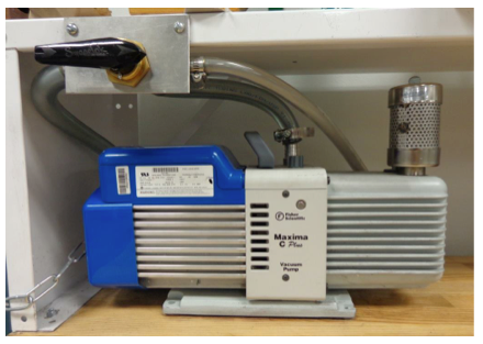
Fig. 13. Vacuum pump and Valve 6.
|
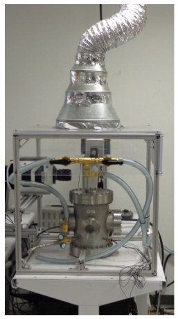
Fig. 14. Chamber and vent.
|
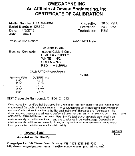
Figure 15 shows the connection diagram for the pressure transducer, while Figure 16 shows its power supply and DAQ installed in Computer 1. The pressure transducer (Omegadyne PX409-030AI, Fig. 8) belongs to the class of two-wire transmitters that work in 4-20mA control loops. It acts like a variable resistor with respect to its input signal (absolute pressure). The transmitter converts pressure into the control signal necessary to regulate the flow of current in the current loop. The level of loop current is adjusted by the transmitter to be proportional to the actual sensor input signal (absolute pressure). The transmitter uses 4mA output to represent the calibrated zero input (0 psi) and 20mA output to represent a calibrated full-scale input signal (30 psi). The calibration worksheet of the used transducer (Appendix 2) provides the following data: 0.00 psia – 4.013 mA, 15.00 psia – 12.026 mA, and 30.00 psia – 20.033 mA. Based on this, the following relationship between pressure and current is recommended: I(ma) = 4.013 + 8.013/15*P(psia). The DAQ measures voltage on the resistor shown in the diagram. The installed resistor is 250 Ohm so that the voltage is the following function of the measured pressure: V(V) = 1.003 + 2.003/15*P(psia). For example, at P = 0 V = 1.003 V and at P = 1 atm (14.7 psia) V = 2.966 V.
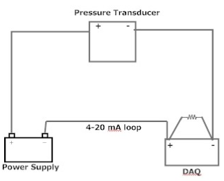
Fig. 15. Connection diagram for the pressure transducer.
|
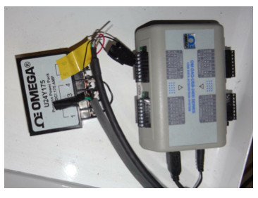
Fig. 16. Power supply and DAQ of the pressure transducer.
|
1.3 Laser
Firestar ti-60 (Fig. 17) is an air cooled 60W CO2 laser (class IV) manufactured by Synrad. The laser is protected from overheating via built-in interlock circuits. The laser generates an infrared beam, which is invisible for a human eye. Listed below are the pertinent laser parameters:
Wavelength: 10.55 – 10.68 µm
Power Output (max): 60 W
Power Stability: ±7 %
Beam Diameter: 2.0±0.3 mm
Beam Divergence: 7.0 mR
Cooling: Air
Heat Load (max): 900 W
Flow Rate, air: 150 CFM x2
Input Voltage: 48 VDC
Input Current: 18 A
Wavelength: 10.55 – 10.68 µm
Power Output (max): 60 W
Power Stability: ±7 %
Beam Diameter: 2.0±0.3 mm
Beam Divergence: 7.0 mR
Cooling: Air
Heat Load (max): 900 W
Flow Rate, air: 150 CFM x2
Input Voltage: 48 VDC
Input Current: 18 A
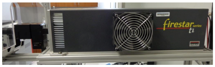
Fig. 17. Synrad Firestar ti-60 laser.
Electric power for the laser is coming from Synrad PS-48 (Meanwell RSP-2400-48) power supply, for which, according to the manufacturer, the required voltage input should be within the range from 180 VAC to 264 VAC, with the following typical values of current and voltage: 15.5 A / 180 VAC and 12 A / 230 VAC. In the laboratory, the power supply is plugged in a 208 V One Phase, 30 A outlet. Figure 18 shows a photograph and a schematic of the connection panel of this power supply. The AC input connectors are AC neutral (labeled AC/N), AC line hot (labeled AC/L), and AC ground. The DC outputs are DC positive 48V+ (red wire) and DC return V- (black wire).
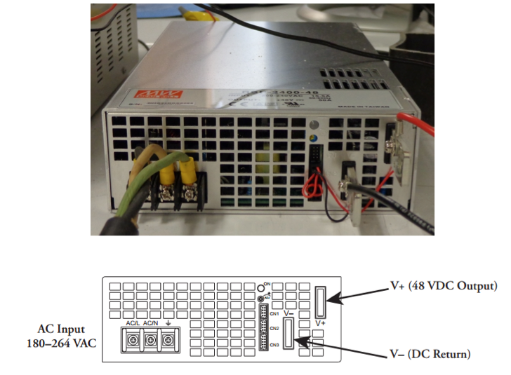
Fig. 18. Connection panel of the laser power supply.
The unit called Synrad UC-2000 controller (Fig. 19) serves for changing the laser power and for turning on/off the laser beam generation. The laser power is varied by rotating a knob. The laser beam generation can be turned on/off by pressing the button “Lase On/Off.” In this setup, however, the UC-2000 is controlled using a computer. The UC-2000 is connected to a 5 VDC power supply (Fig. 20) through a switch (Fig. 21) that is opened and closed with LabView on Computer 1. This allows setting a desired duration of the laser pulse. Figure 22 shows the connection diagram.
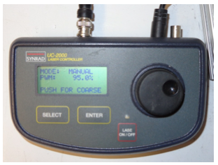
Fig. 19. UC-2000 laser controller.
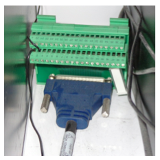
Fig. 21. Switch.
|
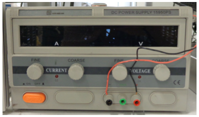
Fig. 20. Power supply connected to UC-2000.
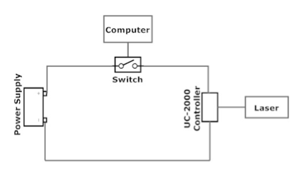
Fig. 22. Connection diagram for UC-2000 laser controller.
|
The laser beam exits from the CO2 laser when all conditions listed below are met:
1. The power supply is plug in to an appropriate electric outlet.
2. The laser key (Fig. 23) is turned on (in horizontal position).
3. The laser shutter is on (Fig. 24).
4. The button “Lase On/Off” on UC-2000 is pressed to “On” (LED is red).
5. The signal is sent from Computer 1.
1. The power supply is plug in to an appropriate electric outlet.
2. The laser key (Fig. 23) is turned on (in horizontal position).
3. The laser shutter is on (Fig. 24).
4. The button “Lase On/Off” on UC-2000 is pressed to “On” (LED is red).
5. The signal is sent from Computer 1.
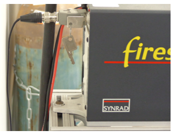
Fig. 23. Laser key (in Off position).
|
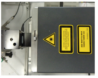
Fig. 24. Laser shutter (in On position).
|
The laser is equipped with a beam delivery system (Fig. 25) which includes a beam bender that changes the direction of the beam by 90° and directs it vertically through the ZnSe window to the sample. The beam is enclosed in the beam delivery system with the exception of a vertical path (16 cm) from the beam delivery system to the ZnSe window.
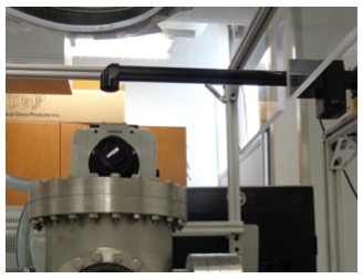
Fig. 25. Beam delivery system.
|
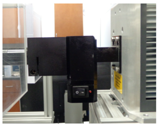
Fig. 26. Laser diode pointer.
|
The laser is equipped with the laser diode pointer (Fig. 26) that generates a red beam aligned with the infrared beam of the CO2 laser. The diode pointer (Class IIIA) was manufactured by Synrad for specific use with Firestar lasers. The diode pointer is used for alignment purposes because the CO2 laser beam is invisible. Listed below are the pertinent parameters of the diode pointer:
|
Wavelength: 650 ± 10 nm
Power Output: < 5 mW Beam Diameter: 3 mm Beam Divergence: < 2 mrad Input Voltage: 3 to 5 VDC Input Current: <50 mA During the experiment or any other operations with the laser (e.g., alignment and measurements of the beam power), the setup should be separated from the room by partitions. Figure 27 shows one of the partitions. Wearing CO2 laser safety glasses is mandatory for the operator and any other people present near the setup (i.e., within the area separated by the partitions). |
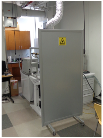
Fig. 27. Partition.
|
2. Operational Procedures
3.1 Preparation and installation of the sample
As noted in Section 2.1, two different sample holders – for solid pellets and for gels/pastes – are used in this setup. The holder for pellets remains inside the chamber unless a gel/paste sample has to be tested. The holder for gel or paste samples should be filled with the sample outside the chamber before each experiment.
All preparation procedures should be done with personal protective equipment (PPE) that includes a respirator and gloves in addition to always required safety glasses/goggles.
A. Preparation of a solid sample
1. Prepare the required amount of each ingredient by measuring the mass with a balance (Mettler Toledo ML 303E).
2. Mix the ingredients in a 3-dimensional inversion kinematics mixer (BioEngineering Inversina 2L) for 60 min.
3. Compact the mixture into cylindrical pellets (diameter 6 mm, height 10-15 mm) using a trapezoidal die (inner diameter 6 mm) and a hydraulic press (Carver).
4. Measure the mass of each pellet using the balance.
5. Measure the height of each pellet.
6. Open the door port of the chamber.
7. Install the pellet on the holder inside the chamber.
B. Preparation of a gel or paste sample
1. Using a balance (Mettler Toledo ML 303E), pour the desired amount of the tested liquid (e.g., deionized water) into a plastic container. Depending on the tested system and the number of samples, the desired amount varies from 1 g to 100 g.
2. Using the balance, prepare the required amount of a gellant (e.g., polyacrylamide powder).
3. Add the gellant to the liquid and mix them manually, using a spatula, for 5 min.
4. Using the balance, prepare the amounts of the tested solid ingredients (e.g., ammonia borane and Al/Mg powder) that correspond to the amount of the obtained gel and the desired mixture ratio.
5. Add the solid ingredients to the gel.
6. Install the container in an acoustic mixer (Resodyn LabRAM) and set the intensity to 50%.
7. Mix for 1 minute.
8. Remove the container from the mixer.
9. Using the balance, measure the mass of the holder with a quartz tube installed.
10. Using the spatula, place the mixture sample into the quartz tube, which is located in the holder.
11. Using the balance, measure the mass of the holder with a quartz tube and the sample.
12. Measure the height of the sample inside the quartz tube.
13. Open the door port of the chamber.
14. Install the holder inside the chamber.
3.2 Alignment of the sample with the laser beam.
1. Check that the CO2 laser is off. The laser key is off (vertical position), the laser shutter is off, the “Lase On/Off” button pressed Off (no light from LED).
2. If this test is the first test this day, plug the laser power supply into the 208 VAC electric outlet. If this test is not the first test this day, the power supply continues to be connected to the electric grid (the laser fans are running).
3. Turn on the laser diode pointer.
4. Looking through the window port, carefully move the holder over the chamber bottom to align the sample with the red beam of the laser diode pointer.
5. Turn off the laser diode pointer.
6. Close the door port of the chamber.
3.3 Programming the laser
1. Turn on computer 1, go to MyDocuments/LaserProgram/LabViewLaser, and start LabViewLaser software.
2. In the software interface, turn on the Boolean switch. Green means on.
3. Set the laser time in seconds.
4. Turn the key on (horizontal position).
5. Open the laser shutter.
6. Check LEDs on the back of the laser. Make sure that all LEDs except for the red one are “On”. The blue (SHT) and yellow (RDY) LEDs mean that the shutter and key are open, respectively. The INT (green) LED means that the interlock circuit is closed and lasing may be enabled. The TMP (green) LED means that the temperature is within the operational limits. Finally, the red LED means that lasing is on.
7. On the UC-2000 controller, set the desired power level (in percent of the maximum).
8. Press the “Lase On/Off” button on UC-2000 so that it is “On” (LED is red). Now the laser is set and ready to be used.
3.4 Pressure transducer
1. On computer 1, open DAQ program in MyDesktop.
2. Open Configuration and turn on channels 1 and 2.
3. Set recording frequency of 50 Hz.
4. In the software interface, press Digital Gauge menu option. The Digital Gauge window opens on the interface.
5. In the Digital Gauge window, increase the number of significant digits to the maximum (6 digits).
6. In the DAQ program interface, press Play icon. The transducer will be measuring the pressure continuously (with no recording).
3.5 Turning on the cameras
High-resolution video camera
1. Turn on computer 2 and open the camera program.
2. Go to settings and set the folder where the file needs to be saved. The camera will start recording upon pressing “Play” button. File will be saved automatically.
Infrared video camera
1. On computer 2, open ExaminIR software.
2. Go to settings and set temperature range 300−1500 °C.
3. Set the desired recording speed in frames per second. The camera will start recording upon pushing “Play” button. File will be saved automatically. If the file format needs to be changed, go to File/Export Video.
3.6 Evacuation and gas filling of the chamber
1. Look at the monitor of Computer 1 that shows the pressure transducer measurements and make sure that the pressure transducer is measuring (recording data is not required at this stage). The transducer should show the actual absolute pressure in the room. Make sure that the indicated pressure is the same as shown by a digital barometer, available in the laboratory.
2. Check valves 1-6 and make sure that valves 1-5 are closed and valve 6 is in the position that connects the vacuum pump with this setup.
3. Open valves 3 and 4.
4. Turn on the vacuum pump and decrease pressure in the chamber to the desired value by checking the readings from the pressure transducer. When a solid pellet is tested, the desired value is 0 psia (1.003 V). When a gel/past sample is tested and liquid is used in the mixture, the pressure cannot be below the saturation pressure of this liquid at room temperature. For example, the saturation pressure of water at RT is 0.4 psia (1.06 V). The desired value of the signal in the evacuation procedure is 1.1 V.
5. Close valves 3 and 4.
6. Turn off the vacuum pump.
7. On the pressure regulator, make sure that the flow pressure control is the “No Flow” position (turned all the way to “Decrease” direction).
8. Open the exit valve of the pressure regulator.
9. Open the valve of the compressed gas cylinder.
10. By rotating the flow pressure control to “Increase” direction, set 10 psi flow pressure on the regulator exit gauge.
11. Gradually opening valve 1, fill the chamber with argon up to an absolute pressure of 1 atm (2.966 V) and close valve 1.
12. Repeat steps 3-6, and 11 two times.
13. Close the valve of the compressed gas cylinder.
14. Turn the flow pressure control all the way to “Decrease” direction.
15. Close the exit valve of the pressure regulator.
3.7 Ignition
1. Check the image in each camera and make sure that the sample is visible. Adjust focus if necessary.
2. Looking at the pressure transducer readings, check that absolute pressure inside the chamber is equal to 1 atm (2.966±0.005 V). If the signal is below 2.961 V, terminate the test by performing steps 3.8 and 3.10; then take measures for decreasing the leak rate. If the signal exceeds 2.971 V, open valves 4 and 5; then, looking at the pressure transducer readings, gradually open valve 3 until the signal becomes equal to 2.966±0.005 V, close valve 3, and then close valves 4 and 5.
3. On Computer 1, in the pressure transducer interface, check “Save Data” box and browse the folder where the file needs to be saved. Press OK.
4. On Computer 2, start recording by the cameras.
5. On Computer 1, in the laser control interface, press the Arrow icon on the Command bar – this will trigger lasing for the preset duration.
6. Observe the process on the monitor of Computer 2.
7. After the combustion front has reached the bottom of the sample, stop video recording by pressing Stop button in the windows for both cameras on Computer 2.
8. On Computer 1, in the pressure transducer interface, stop pressure recording by pressing Stop button.
3.8 Turning off the laser
1. Press the “Lase On/Off” button on UC-2000 controller so that lasing will be off.
2. Close the laser shutter.
3. Turn the key located on the back of the laser to the “Off” position (vertically). Check that the “rdy” yellow LED on the back of the laser is off.
4. If this test was the last test on this day, disconnect the laser power supply from the grid.
3.9 Mass-spectroscopic analysis
1. Make sure that valves 1 to 5 are closed.
2. On the front panel of the mass-spectrometer, check pressure. “System OK” means that there is a sufficient vacuum in the MS. If the front panel shows “Pressure OverRange,” pressure is too high. In this case, go to Functions and pump the system down and wait until “System OK” appears.
3. If “System OK” is shown, go to Functions, turn MS heaters on and open the inlet valve inside the MS.
4. Turn on computer 3 and open Quadera software.
5. In Quadera interface, turn on Filament and SEM.
6. Set type of scan (Analog or MID scanning). Analog scanning shows all gases available in the gas sample, but it is not recommended for accurate measurements of specific gas concentrations. MID scanning analyses gases that are specified by the operator and it is used for accurate measurements of their concentrations.
7. Open valve 2.
8. In Quadera interface, press Play for measurements.
9. When the measurements become stable, press Stop on Quadera interface.
10. Close valve 2.
3.10 Opening the chamber
1. Open valves 3, 4, and 5.
2. On the pressure regulator, make sure that the flow pressure control is the “No Flow” position (turned all the way to “Decrease” direction).
3. Open the valve of the compressed gas cylinder.
4. Open the exit valve of the pressure regulator.
5. By rotating the flow pressure control to “Increase” direction, set 10 psi flow pressure on the regulator exit gauge.
6. Gradually opening valve 1, purge the chamber with argon for 2 min, maintaining the atmospheric pressure in the chamber. Then, close valve 1.
7. Close the valve of the compressed gas cylinder.
8. Turn the flow pressure control all the way to “Decrease” direction.
9. Close the exit valve of the pressure regulator.
10. Close the gas cylinder stem valve.
11. Open the door port of the chamber and remove the sample.
3.11 Calibration of the mass-spectrometer
1. Calculate several pairs of partial pressures of argon and the calibrating gas (PAr,1 and Pgas,1; PAr,2 and Pgas,2; PAr,3 and Pgas,3; etc.) in the binary mixture Ar-gas at 1 atm that correspond to the several points on the calibration curve in the vicinity of the expected gas-Ar mixture ratio in the product gas mixture.
2. Connect the chamber to the pressure regulator of the compressed argon cylinder.
3. Three times evacuate and fill the chamber with ultra-high purity argon at 1 atm (2.966±0.005 V) absolute pressure following the procedure described in Section 3.6.
4. Open valves 4 and 5.
5. Gradually opening valve 3, set the absolute pressure of argon, with 0.05% tolerance, in the chamber to be equal to the partial pressure of argon in the selected pair of partial pressures (see step 1).
6. Close the gas cylinder stem valve.
7. Disconnect the pressure regulator of the argon cylinder and connect the calibration gas cylinder through its pressure regulator.
8. On the pressure regulator of the calibration gas cylinder, make sure that the flow pressure control is the “No Flow” position (turned all the way to “Decrease” direction).
9. Open the exit valve of the pressure regulator.
10. By rotating the flow pressure control to “Increase” direction, set 10 psi flow pressure on the regulator exit gauge.
11. Gradually opening valve 1, add the calibrated gas to the chamber so that the total absolute pressure is equal to 1 atm (2.966±0.005 V). Then, close valve 1.
12. Close the valve of the compressed gas cylinder.
13. Turn the flow pressure control all the way to “Decrease” direction.
14. Close the exit valve of the pressure regulator.
15. Wait for 5 min for a better mixing of the calibration gas with argon.
16. On Computer 3, open Quadera software.
17. Start the multiple ion detection (MID) program.
18. Open Valve 2. The mass-spectrometer will read an electric current (in Amps) for the calibration gas.
19. Stop MID.
20. Close Valve 2.
21. Disconnect the pressure regulator of the calibration gas cylinder and reconnect the pressure regulator of the argon cylinder.
22. Repeat steps 2-20 several times, setting different argon pressures in step 5, which correspond to argon partial pressures calculated in step 1. This will produce several points that will be used for building the calibration curve.
4 Analysis of Hazards and Existing Safety Measures
4.1 Pressure
There is a hazard that gas pressure in the chamber will exceed the value at which one of the windows breaks, leading to a shock wave and ejection of glass fragments. This may happen in two situations:
· Pressure increase caused by combustion is too high.
· During filling the chamber with argon, the operator increases pressure too much.
The existing countermeasure for the first situation is the calculations of the sample mass that will lead to the maximum allowed pressure increase. This measure is insufficient because a mistake can be made in the calculations and also the mixture may contain unknown impurities that will be volatized during combustion.
Since neither a pressure relief valve nor a rupture disk is installed, the only countermeasure for the second situation in the analyzed setup is discipline and accuracy of the operator. This measure is insufficient because a human error is always possible.
Analysis of the gas filling/evacuation system (Fig. 9) also revealed an unnecessary valve (#4). Three valves (3, 4, and 5) should be opened for connecting the chamber with the atmosphere. This complicates the operation and increases the probability of a human error. The connection scheme is not optimal; it can be simplified so that only one valve needs to be opened for connecting the chamber with the vent line.
Further, there is no valve near the chamber that closes the line to the vacuum pump. The pump is located at some distance from the setup and valve 6 is located near the pump (Fig. 13). If the operator forgets to switch this valve to the position that disconnects the pump from the setup, opening valves 3 and 4 will lead to exiting gas from the chamber to the pump and then to the atmosphere.
Finally, the exit pipe from the setup is not firmly attached to the inlet of the vent. Because of this, purging the chamber with argon may lead to contaminating air in the room by reaction products.
4.2 Laser
In the beam delivery system, there is a 16-cm gap where the beam is not enclosed (Fig. 25). During the development and testing of the setup, a beam collimator was used to expand the beam diameter by three times. The collimator was installed where now the gap is. Testing has shown, however, that the ignition is better without the collimator so that it was removed. The existing gap increases hazard because the operator may incidentally place a hand or some object there during laser beam generation.
The manufacturer has not provided “Open/Close” labeling for the laser shutter (Fig. 24).
In the laser power supply, the power input connectors (208 VAC) are not covered (Fig. 18) so that the operator may touch them and be electroshocked.
3. Recommendations for Improving Safety in the Setup
4.1 Pressure
The gas filling/evacuation system must be changed. Specifically, the following changes are recommended.
A pressure relief valve for 10 psi and a rupture disk for 15 psi should be installed.
The unnecessary valve 4 (Fig. 9) should be removed. The scheme should be further simplified, leading to a lower number of valves and hence a lower probability of a human error. Figure 28 shows a possible solution. Valves 1-4 are precise needle valves.
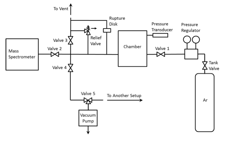
Fig. 28. Schematic of the proposed gas filling/evacuation system
The exit pipe from the setup should be firmly attached to the inlet of the vent so that the gas flows directly into the vent.
4.2 Laser
A metal tube should be installed vertically to eliminate the 16-cm gap in the beam delivery system so that the beam will always be enclosed.
“Open/Close” labeling should be made for the laser shutter.
In the laser power supply, the power input connectors (205-220 VAC) should be covered for eliminating the possibility of touching them.
Appendix. Calculations of the Maximum Allowed Mass of the Sample
During combustion of the mixture sample, pressure in the chamber increases because of two factors: (1) the increase in the mass of gas inside the chamber due to gas generation by the mixture and (2) the increase in the temperature of the gas inside the chamber caused by combustion heat release. The temperature increase is temporary because the gas mixture inside is cooled down to room temperature owing to heat losses to the chamber walls. The calculations, however, should be conducted for the maximum temperature of the gas.
The constraint for the gage pressure in the chamber is 10 psig. All experiments are conducted in an argon environment at 1 atm (14.7 psia) absolute pressure. The mass of gas that, being added to the argon in the chamber, will increase pressure to 10 psig, is calculated using the ideal gas equation:
mgas=(Mgas V)/(Ru T)(Pa+∆P-PAr) (1)
where Mgas is the molar mass of the evolved gas, V is the volume of chamber (11.35 L), Ru is the universal gas constant (8.314 kJ·kmol−1·K−1), T is the gas temperature, Pa is atmospheric pressure, ∆P is the allowed gage pressure (10 psig = 68.9 kPa), and Par is the pressure of argon at room temperature (1 atm = 101.3 kPa). For simplicity, atmospheric pressure is assumed to be equal to 90 kPa.
The mixture typically includes a compound that is a source of the gas and the additive that provides energy for decomposition of the gas source.
If the mass of gas is known, the mass of decomposed source of this gas is determined from the equation:
mcomp=Mcomp/(nMgas ) mgas (2)
where Mcomp is the molar mass of the compound and n is the number of moles of the gas per mole of compound.
The mass of the sample can then be calculated from the equation;
ms=mcomp/mfcomp (3)
where mfcomp is the mass fraction of the gas source in the mixture sample.
In Eq. 1, temperature depends on the combustion heat release as well on the masses and specific heats of the released gas and argon. It is recommended that two cases are considered in the calculations. In the first case, it is assumed that the sample includes only the source of gas and the gas remains at room temperature. In this case, we calculate the mass of the compound using Eqs. 1 and 2, and the mass of the sample is equal to the mass of the compound.
In the second type, the mixture has the highest concentration of the energetic additive within the tested range of the mixture ratios (the amount of gas per unit mass of the mixture is less than in the first case, but the temperature is high). The gas temperature is calculated from the energy balance:
T=(c(v,gas) mgas Tad+c(v,Ar) mAr To)/(c(v,gas) mgas+c(v,Ar) mAr ) (4)
where To is room temperature, mAr is the mass of argon in the chamber, calculated by the formula:
mAr=(PAr VMAr)/(Ru To ) (5)
and Tad is the adiabatic flame temperature for the mixture at 1 atm, calculated using THERMO (version 4.3) software, available in the laboratory. In this case, first, Tad is calculated using THERMO, then the mass of gas is calculated using Eq. 1 assuming that T=To, then the mass of argon is calculated from Eq. 5, then temperature is calculated from Eq. 4, then the next iteration is conducted for Eq. 1, and so on, until the temperature difference in two subsequent iterations becomes less than 100 K.
After the calculations have been conducted for the two cases described above, the smaller sample mass of the two obtained values is selected.
Then, the safety factor of 2 is introduced and hence 50% of the selected mass is considered to be the maximum allowed mass of the sample.
Appendix 2. Certificate of Calibration for the Pressure Transducer