MICRO-MOUSE PROJECT
Daniel Rodriguez, Jose David Cruz, Alberto Delgado, Rene Gabaldon, Alejandro Garcia, Pedro Guerra, Jesus Mendoza, Jose Soto, Gabriel Trujillo
Work Distribution
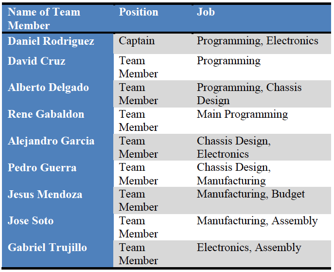
The work distribution among the team members was a key factor in the process of designing and building our micromouse. The work distribution was the following:
At the end of the project, even when we all had a specific job assigned, every member contributed in some way to each part of the micromouse, making this project a good experience for us, especially when it came to work in teams.
Background
The Micromouse Competition is a small event that began in the late 1970s. This event consists of designing and building a small robot that is capable of solving a 16x16 feet maze. The Micromouse competition is held worldwide, it includes countries like UK, US, Japan, Singapore, India, and South Korea. The robots have to be completely autonomous and have to find their way to the goal without any assistance, like a remote control. The robots are allowed to run the maze in order to figure out the shortest route to the goal. There is a second run held, this time the robots know their way to the goal, they achieve this by using mapping. In this second run the robots are timed, the one that completes the maze in the shortest time wins.
Objective
Our design is not as sophisticated as competition robots, mainly because we do not have the time, the experience, or the budget that competition teams have. Our robot uses a simpler level of intelligence, however it should be able to solve both mazes without any complication in a reasonable time, considering that the maze that our robot will solve only measures 6X6 feet. We were provided with a $400 budget by the Mechanical Engineering department. With this budget we bought the necessary components for our robot, which include the servomotors, microcontroller, sensors, wheels, batteries, and any material necessary for the construction of a chassis.
Components
When you are doing a micro mouse you really do not know where to start. Here we are going to give a brief explanation of what we need to make a micro mouse. First, the chassis that is our base or structure that support all the elements that make the micro mouse work. The most important task that has to be solved choosing the micro mouse frame is to take in consideration its weigh, its carrying weight distribution. Also, this material is better if do not transmit electricity so we can avoid non desired contacts. Indeed, the micro mouse needs its motors. In order to choose good motors, we took in account tree main things its weight, its torque, and the angular velocities that could be provided. Another thing that we took in account to make a good micro mouse design, we carefully choose a good microcontroller. The most important consideration that we look for was the easy management of the microcontroller, the easiest to understand. Indeed, we had also to choose good wheels. The most important factors that we were looking for on the wheels were average size, so the torque and the velocity give us good efficiency. In addition, we had to choose good eyes for the micro mouse. This is our sensors. In this part we were looking for some sensors which work better in short distances. Another key part was the pc board that is where we make the connections of everything. Finally, last but not the least important we choose the power source. For our power source we took in consideration its voltage capacity, and its weight. In brief we had to choose very carefully the materials that we used, However, we do not just take in account the materials capacities, we also take in account the physical properties of the different parts used , so we could get the higher efficiency of the each part. In the following pages we are going to give a more deeply information about the characteristics of each part of the micro mouse and parameters that we use in order to choose the better we could.
Sensors
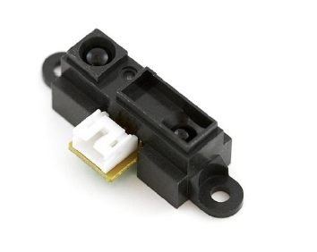
There was a variety of sensors to choose from in the market. Some of the sensors available were infrared and ultrasonic. We ended up choosing Sharp Infrared sensors because of their short distance capability of sensing and precision. These types of sensors have detection capabilities that range from about 4cm to 30cm. The operation voltage varies from 4.5V to 5.5V and the average current consumption is about 33mA. The signal output type is analog and its response time is around 38 milliseconds with a variation of plus or minus 10 milliseconds.
Motors
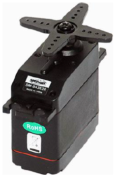
For the motors we the option of getting DC, servos, and stepper motors. In the end, we chose servo motors for many reasons. We considered the torque, as they were required to go up the ramp, the difficulty to program the motors, which wasn’t high, and the price. The SM-S4303R is a standard size servo built for continuous rotation which can give up to 70 rpm at 6 volts. We chose it because it was a user friendly for beginners in programing and it was compatible with the Arduino micro-controller. Its torque is about 4.8kg/cm, which was enough to up the ramp which had an incline of about 45 degrees.
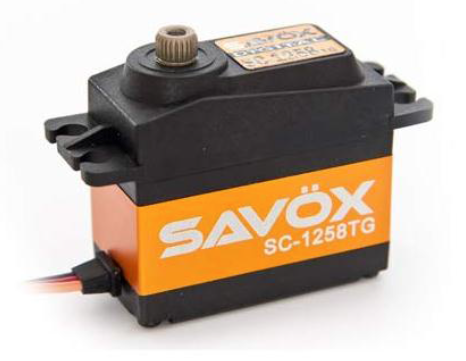
After the testing sessions that all of the groups had together and that noticing that the robots of some of the other groups were faster, and more powerful, we decided to replace our low cost servos with more powerful ones. For the new motors we chose the Savox sc-1258TG servos. We did this because these servos were more efficient and could develop more speed and torque. Its gears were made out of titanium and aluminum; they are very light and resistant unlike the plastic gears of the old servos. This new servos have a voltage range of about 4.5 to 6 volts. Their torque at 4.8V is 9.6kg./133.3oz-in and at 6.0V the torque increases to 12.0kg/166.6oz-in. The only downside of these servos was that they didn’t have continuous rotation, like our last servos, they only rotated 180 degrees, so we had to open them up and modify them. The modification process started with us unbolting the frame of the servos. We then had to take the gearing system out in order to have space to maneuver. After this was done, we removed the stopper that limited the rotation of the servos. Like any other servo, this new servos had a potentiometer, an adjustable voltage divider, but unlike our old servos, this ones were limited to 180 degrees. We removed this limited potentiometer and added a potentiometer to each new motor. The new 360 degree potentiometers we acquired were removed from the old motors, which we also had to disassemble in order to get them. After this tedious process was over, we had a positive result, for the newly modified motors had continued rotation, a higher speed, and a higher torque.
Wheels
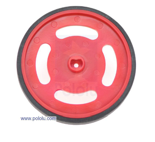
A critical component we had to select was the wheels. This component was very important because the size of the wheel, including the tire, highly affected the displacement of the micromouse as a whole. We picked this wheels because of their affordable price and because their size in diameter, which was 2 3/8 inches, seemed reasonable for our purpose.
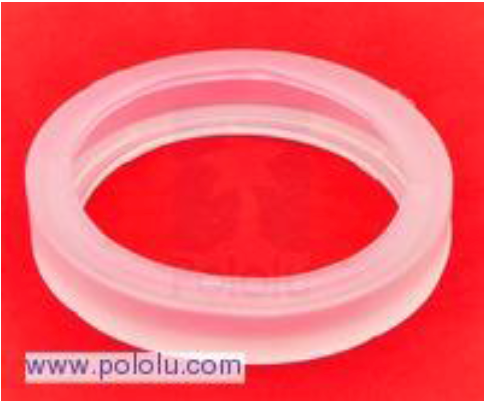
After intensive testing, these tires proved to be efficient enough at first, but as they got dirty and got used up, the robot started to slip. This became a serious issue when we were required to go up the ramp. We discussed whether it was necessary to replace the tires or not. We ended up deciding to replace them with high traction sticky tires. The purchase of these new tires proved to be the right decision. With the increased area of contact between the floor and tire, the new tires rarely slipped, and were very helpful in our goal of going up the ramp.
Controller
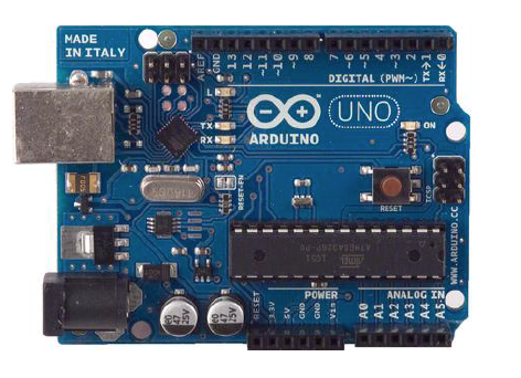
For the selection of the controller, we went ahead and chose the recommendation of the TA, which was an Arduino. The Arduino is a popular open-source single-board microcontroller, designed to make the process of using electronics in multidisciplinary projects more accessible. The hardware within the Arduino consists of a simple open hardware design for the Arduino board with an Atmel AVR processor and on-board input/output support. The software consists of a standard programming language compiler and the boot loader that runs on the board. We bought the Arduino Uno Starter Kit; it came with the microcontroller, its sub cable, a few sensors
that we didn’t use, its own breadboard, which later we replaced with a bigger one, and a few resistors. The Arduino was easy to use and its programing was similar to the C++ code.
that we didn’t use, its own breadboard, which later we replaced with a bigger one, and a few resistors. The Arduino was easy to use and its programing was similar to the C++ code.
Power Supply
One very important aspect to the performance of the micro mouse is the power supply to both the arduino microcontroller and the motors. He had a few options concerning the selection of the most appropriate power supply; we took into consideration the use of lithium rechargeable batteries or alkaline batteries. One of the attractive aspects regarding lithium rechargeable batteries was that there is no need to buy new batteries every time we ran out of battery, yet the drawback was that while running low the lithium rechargeable batteries don’t give enough power to the motors or the arduino and you don’t get a good response in your micro mouse robot. In the other hand even though the alkaline batteries must be changed every time they run out of energy they give a consistent power supply so you always get the desired power input for the micro mouse robot. At the end we decided to go with the alkaline batteries because we figured that even though we would have to replace them every now and then, it was the most reliable and
simple form of power supply. We used a 9 volt battery for the power of the arduino and we used four AA 1.5 volt batteries connected in series to supply enough power to the motors.
simple form of power supply. We used a 9 volt battery for the power of the arduino and we used four AA 1.5 volt batteries connected in series to supply enough power to the motors.
Budget
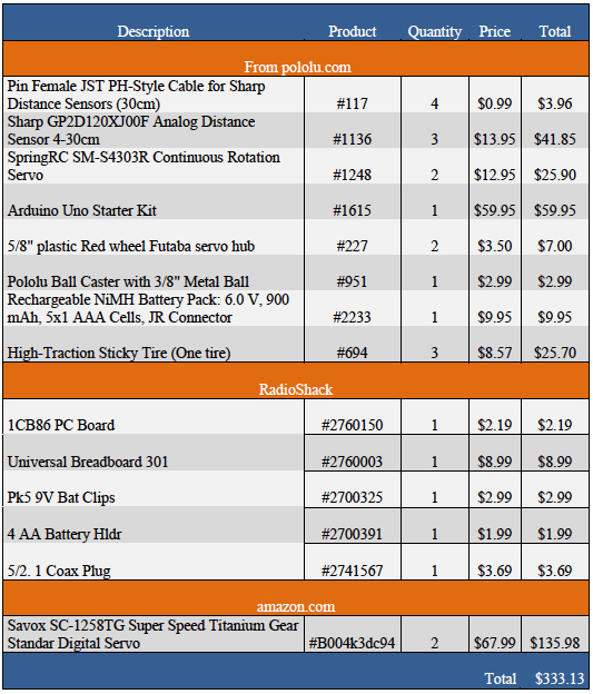
With the money provided we managed to buy all the components needed. Here is a list of what we bought: Description
Programming
Competition micromouse robots consist of a complex programing; which includes maze mapping and recognition. After a short run in the maze these robots create a virtual map of the maze and determines the shortest way to the goal. This type of programing takes years to master. Without any previous experience it is virtually impossible to develop this programing.
In order to solve the maze we had to create a simpler logic. We are using Arduino Uno microprocessor; therefore we had to use Arduino 1.0 software. Our logic is fairly simple but efficient for this project. By following a single wall all the way our robot should be able to get to the goal; we selected the right wall. In order to complete this task we used three analog distance sensors; two on the right side and one in the front. The to sensors in the right side have two main functions. One is to detect the wall to run along; if there is not our robot should turn right. The other function is to self-adjust to the wall; by comparing the distance to the wall from both sensors our robot adjusts its path so that it goes as parallel as possible to the wall.
In order to solve the maze we had to create a simpler logic. We are using Arduino Uno microprocessor; therefore we had to use Arduino 1.0 software. Our logic is fairly simple but efficient for this project. By following a single wall all the way our robot should be able to get to the goal; we selected the right wall. In order to complete this task we used three analog distance sensors; two on the right side and one in the front. The to sensors in the right side have two main functions. One is to detect the wall to run along; if there is not our robot should turn right. The other function is to self-adjust to the wall; by comparing the distance to the wall from both sensors our robot adjusts its path so that it goes as parallel as possible to the wall.
Basics
Right turn: it is done by reducing the speed of the right wheel and increasing the speed of the left wheel. After the side sensors stop sensing the wall the robot turns right, followed by a forward delay so that it aligns to the new wall’s path.
Left turn: using the left motor in reverse and the right motor forward allows our robot to turn left in a reduced space. It happens when all sensors including the front senor sense a wall; this means that the robot is at a dead end or can only go left. In either case the robot does not need a forward delay like in right turn, this means it keeps sensing in the same spot.
Adjusting: by increasing the speed on either motor our robot can correct its path to be parallel to the wall. By comparing the distance to the wall of both sensors (S1 front sensor S2 back sensor) the robot can increase the speed of the motor required: if distance in S1>S2 the robot is getting away from the wall, then the speed of the left motor is increased to get closer. If the distance S1<S2 it means that the robot is getting closer to the wall, increasing the speed in the right motor will get it back on track.
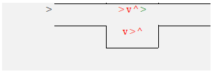
Maze configurations
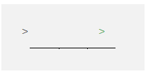
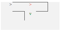
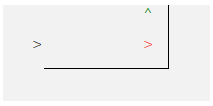
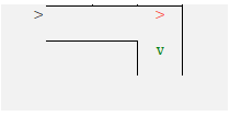
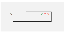
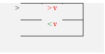
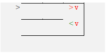
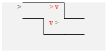
> Initial point
> Sensing/ stopped sensing/ forward delay/ adjusting
> Correct path/ solution
The robot never stops sensing the wall, solution continues going forward.
The robot is going forward and stops sensing the right wall, solved by doing right turn.
The robot goes forward keeps until it starts sensing the wall up front, solution it turns left.
The robot stops sensing the right wall, which has higher hierarchy than sensing front wall. Solution it turns right.
The robot runs into a dead end, solution it turns left twice. The robot senses both right and front wall, turns left. Since it continues sensing both walls turns left again.
The robot stops sensing the right wall, turns right. After the delay it still does not sense a right wall turns right again.
The robot stops sensing the right wall, turns right. After the delay it still does not sense a right wall turns right again. Front wall has no effect.
The robot stops sensing right wall and turns right, the front wall has no effect. After forward delay senses both right and front wall and turns left.
The robot stops sensing right wall and turns right. After the forward delay, senses both right and front wall and turns left. Continues forward and runs to another front wall turns left again. Finally stops sensing right wall and turns right, this time front wall has no effect.
IF statements
The if statement are set of commands to that take a certain input and produce a given output. It is a closed loop control system, meaning that it changes the output based on the difference of the feedback signal and the input signal. You can see the complete code and commands in attachment 1. All the if statements are described ahead:
Continuous wall
if((distance1 >6) && (distance2 >1.8) && (distance2 <2.8)) //Full speed ahead
When there is an opening in the right wall
if(distance2 >9) //openeing to right, turns right
To adjust, separating from the wall
if((distance1 >6) && (((distance2 >2.8) && (distance2 <9)) || (distance2 >(distance3 +0.2)))) //Starts going right if not parallel
if(distance2 <(distance3 -0.3))
When there is an opening in the right wall while adjusting
if(distance2 >9) //openeing to right, turns right
When it adjust more than enough
if((distance1 >6) && (distance2 <1.8)) //stop, reverses, adjusts to left(timed), forward
To adjust, getting closer to the wall
if((distance1 >6) && ((distance3 -0.3) >(distance2 +0.5))) //starts going left if not parallel
if((distance3 -0.3) <distance2)
if(distance1 <6)
When there is no right opening and a front wall
if(distance2 <9) //if no openeing to right and wall ahead, turns left
To overwrite previous statement when opening to the right
else if(distance2 >9) //if opening to right and wall ahead turn right
Design of Micro-mouse Chassis
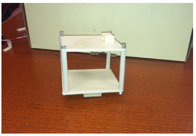
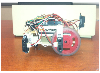
The picture above shows the design that the team first came up with. We decided to go for this first design because we wanted to make it compact so it could have space to maneuver around the maze. We gave it two levels, in the lower lever we placed the servos and the batteries, and in the upper level we placed the microcontroller and the bread board. We placed the sensors in an L shape bracket in order to have them stick out of the chassis; this helped us get them stable in order to get appropriate readings. One problem we encountered with design was that there was barely any room for the components. Another problem was that as it went through
the ramp it would flip over to the front, since the body was too small and weight was concentrated in the front, this would cause the micro mouse to flip.
the ramp it would flip over to the front, since the body was too small and weight was concentrated in the front, this would cause the micro mouse to flip.
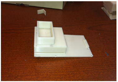
In the picture above we show the second model we came up with. What we tried to do in this iteration was to distribute most of the weight to the back, so as it went through de ramp it wouldn’t flip. In redesigned chassis we moved the batteries to the back, and we placed the microcontroller in the top level which is not shown in the picture. The sensors were again placed with an L shape brackets that were screwed to the body. The problem we encountered with this model was that there was too much weight in the back. The ball caster would get stuck and the micromouse would have too much trouble moving, sometimes it didn’t even move at all. So again we decided to come up with another model for the micromouse in which we would have to distribute the weight along the body by making some changes to it.
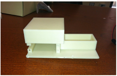
This was our third design which we thought was going to be our last. In this one we moved some of the weight to the back by moving the 9 volt battery. We placed the servos in the front (left in picture) and above them the 4 AA batteries and the microcontroller. We also placed the sensors in the body with the L shape brackets that were held in place with screws. With this model we thought that the weight distribution problem was going to be solved, but when the micromouse went through the ramp it flipped to the front again, like in our first design. It did this all the times it went through it, unlike the other models which sometimes they did pass the ramp without flipping which depended on the speed that the robot was moving at. So again we had to iterate the design in order to solve this weight distribution problem.
This was the last model we came up with. In this design we moved the double AA batteries together with the microcontroller towards the middle of the body. The 9 volt battery was left as in the previous design as well as the servo motors in the front. The sensors as you can see in the picture we attached as in the previous designs with the L bracket screwed to the body. The problem we had with this model was that with this weight distribution the tires were slipping. The solution we came up with was to add two small stainless steel bars; one small weight was placed in front on the servos and the other weight was placed behind the servos and in front of the 9V battery. With this set up the tires wouldn’t slip and the micromouse didn’t flip while going through the ramp. But doing this as it went through the ramp with this extra weight in the front it flipped over. So we added another small stainless steel bar in the back to compensate.
Conclusion
To conclude, this micromouse project really helped us to develop our electronics and programing skills. Even though we faced different problems during the assembling, designing and programing parts, the good thing was that we meet the goals stated at the beginning of the semester. At the competition, our micro mousecwas one on the two robots that solve both mazes.
There were gained more insights of how a team project, like this one, should perform. Where the designing should meet certain electronic and program expectations, and vice versa. The project created a real world job situations, as well as a real world experiment.
Finally, the most important thing we thought was good for the project, was that we just don’t make the micromouse to work. We also do what an engineer does, we optimized our model. Starting with the simplest design, and ending with the best design after having tried more than 2 designs. The optimizing part of the project was a useful tool, for the completion of the project.
Appendix
Arduino Code
#include <Servo.h>
int IRpin1 = 0; //IR sensor1 in analog pin 0
int IRpin2 = 2; //IR sensor2 in analog pin 2
int IRpin3 = 4; //IR sensor3 in analog pin 4
Servo servoR; // create right servo looking from back of robot
Servo servoL; // create left servo looking from back of servo
void setup()
{
pinMode(13, OUTPUT); //Setting LED as output
pinMode(11, OUTPUT); //Setting LED as output
pinMode(9, OUTPUT); //Setting LED as ouput
pinMode(7, OUTPUT); //Settin LED as output
Serial.begin(9600); // start the serial port
servoR.attach(3); // attaches servoR to digital pin 3
servoL.attach(5); // attaches servoL to digital pin 5
}
void loop()
{
float volts1a = (analogRead(IRpin1)); //These 6 lines get the output of the sensors
float volts2a = (analogRead(IRpin2)); //These 6 lines get the output of the sensors
float volts3a = (analogRead(IRpin3)); //
delay (40);
float volts1b = (analogRead(IRpin1));
float volts2b = (analogRead(IRpin2));
float volts3b = (analogRead(IRpin3));
delay (40);
float volts1c = (analogRead(IRpin1));
float volts2c = (analogRead(IRpin2));
float volts3c = (analogRead(IRpin3));
delay (40);
float volts1d = (analogRead(IRpin1));
float volts2d = (analogRead(IRpin2));
float volts3d = (analogRead(IRpin3));
delay (40);
float volts1e = (analogRead(IRpin1));
float volts2e = (analogRead(IRpin2));
float volts3e = (analogRead(IRpin3));
float distance1 = (1000/((volts1a +volts1b +volts1c +volts1d +volts1e) /5));
float distance2 = (1000/((volts2a +volts2b +volts2c +volts2d +volts2e) /5));
float distance3 = (1000/((volts3a +volts3b +volts3c +volts3d +volts3e) /5));
Serial.println(distance1);
Serial.println(distance2);
Serial.println(distance3);
if((distance1 >6) && (distance2 >1.8) && (distance2 <2.8)) //Full speed ahead
{
servoR.write(19);
servoL.write(165);
if(distance2 >9) //openeing to right, turns right
{
servoR.write(19);
servoL.write(165);
delay(200);
servoR.write(90);
servoL.write(90);
delay(500);
servoR.write(92);
servoL.write(92);
delay(1100);
servoR.write(19);
servoL.write(165);
delay(800);
servoR.write(90);
servoL.write(90);
delay(500);
}
}
if((distance1 >6) && (((distance2 >2.8) && (distance2 <9)) || (distance2 >(distance3 +0.2)))) //Starts going right if not parallel
{
servoR.write(90);
servoL.write(92);
if(distance2 <(distance3 -0.3))
{
servoR.write(19);
servoL.write(165);
}
if(distance2 >9) //openeing to right, turns right
{
servoR.write(19);
servoL.write(165);
delay(200);
servoR.write(90);
servoL.write(90);
delay(500);
servoR.write(92);
servoL.write(92);
delay(1100);
servoR.write(19);
servoL.write(165);
delay(800);
servoR.write(90);
servoL.write(90);
delay(500);
}
}
if((distance1 >6) && (distance2 <1.8)) //stop, reverses, adjusts to left(timed), forward
{
servoR.write(90);
servoL.write(90);
delay(500);
servoR.write(92);
servoL.write(88);
delay(1000);
servoR.write(88);
servoL.write(90);
delay(500);
servoR.write(19);
servoL.write(165);
delay(400);
}
if((distance1 >6) && ((distance3 -0.3) >(distance2 +0.5))) //starts going left if not parallel
{
servoR.write(88);
servoL.write(90);
if((distance3 -0.3) <distance2)
{
servoR.write(19);
servoL.write(165);
}
}
if(distance1 <6)
{
servoR.write(90);
servoL.write(90);
delay(500);
if(distance2 <9) //if no openeing to right and wall ahead, turns left
{
servoR.write(92);
servoL.write(88);
delay(300);
servoR.write(90);
servoL.write(90);
delay(500);
servoR.write(88);
servoL.write(88);
delay(1390);
servoR.write(90);
servoL.write(90);
delay(500);
servoR.write(19);
servoL.write(165);
}
else if(distance2 >9) //if opening to right and wall ahead turn right
{
servoR.write(19);
servoL.write(165);
delay(200);
servoR.write(92);
servoL.write(92);
delay(1100);
servoR.write(90);
servoL.write(90);
delay(400);
servoR.write(19);
servoL.write(165);
delay(800);
servoR.write(90);
servoL.write(90);
delay(500);
}
}}
