DESIGN OF AN EXTERNAL FIXATOR
Alfonso Hidrogo, Daniel Rodriguez, Jorge Moreno, Jonathan Minjares, and Juan Duran
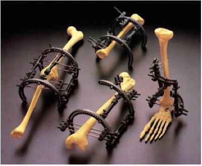
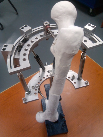
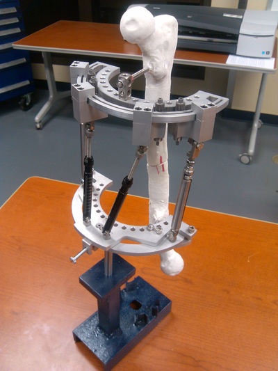
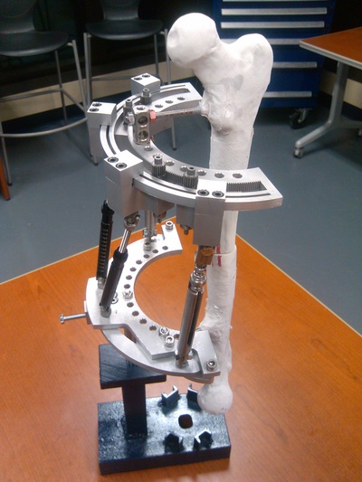
Bone deformities and many breakage injuries require surgical treatment using external fixation systems in order for the bone to heal properly. As for right now, circular fixator devices such as the Taylor Spatial Frame (TSF) are the ones which do get the job done without surgical soft tissue separation procedures. However, these circular systems bring some issues through the healing process; the most significant one being the interference when getting x-ray images. Furthermore, these structures cause comfort problems to patients which in some cases may be really hard to bear. Because of these reasons the improvement in the current systems is essentially becoming a need. With this in mind, the MoD (Masters of Design) team performed extensive research, simulations, models, experiments and prototype constructions in order to ultimately come up with a revolutionary design. The new design’s most significant upgrade presented in this report compared with circular external fixators such as the TSF is the reduction from the complete circle to half a circle. Along with this change the addition of several components is fundamental; however, other components were kept because of their already working functionality. Consequently, the new OnePiece frame will be able to heal bone deformities and breakages without interfering during x-ray images and it will significantly improve the patient’s comfort.
1. Introduction
The MoD team under the guidance of Dr. Noe Vargas from the Mechanical Engineering Department at UTEP proposed the idea of a new design for an external fixation orthopedic device. This new design is an evolution of the Taylor Spatial Frame (TSF) which is the most popular external fixation device nowadays. The new design’s challenges are to be half a circle and ergonomic in order to achieve two major goals; making the patients recovery process as comfortable as possible and improving the design in order for the medical staff to take x-rays easier. Consequently, the OnePiece fixator will have additional and complex components in comparison with the TSF simply because it is more compact although it covers the same functionality. This report will describe the justification for the design of the OnePiece fixator as well as discuss the processes and methods utilized with the purpose of generating a new external fixator.
2. Design Process
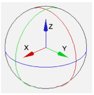
The most important parameter regarding the dynamic capabilities of the OnePiece fixator is that the new design remains having six degrees of freedom (dof). Furthermore, Dr. Amr provided specific measured movements to have as a minimum in the device. To explain these movements a determinate z-y-z coordinate system is required for guidance, the requested limits are the following:
*Note: This coordinate system will be used as reference throughout the whole report |
3. Primary Components
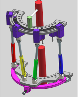
Having these parameters taken into consideration the ideas introduced to achieve them managed to generate a clever design which completely takes care of the specifications above. This design includes four struts, three plates and a gear system. After several design iterations The OnePiece external fixator’s unigraphics NS 7.5 CAD drawing full assembly is the following:
|
Before breaking it into its primary pieces, please note that the red cylinders represent the patient’s broken bone. Now, in this model one may visualize the gear system in the top plate and the connection to the bone. The four struts connect the top plate with the bottom part of the fixator; they also carry the clamps and lock systems in the top. The middle plate connects to the other part of the broken bone. Finally the pink figure is the bottom plate, which is connected to the middle one. Other even smaller components help the connections and structural endurance; for instance, the bottom screw or the bottom retainers.
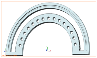
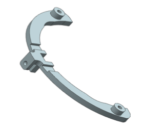
As stated above, the OnePiece fixator contains extra and complex parts when comparing it with the TSF, for this reason, it is fundamental to explain how these parts assemble with the main structure and their role as an operational structure. The main structure may be subdivided into five different main pieces which have several components themselves. These five parts are: The top plate, the clamps, the struts, the middle plate and the bottom plate. The following are brief descriptions of the main components already mentioned:
|
3.1 Top Plate
3.2 Clamps
|
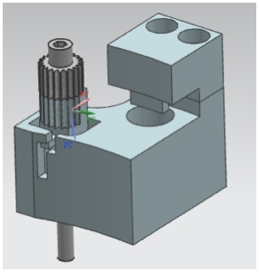
The clamps are what connect the top plate with the four struts. In addition, the clamp includes the gears and the lock system. One of these two components is in constant contact with the top plate gear. Whether is the gear itself or the lock part, which is the half circle gear on the bottom of the gear itself, there is always contact with the top plate. In any case, the clamp also connects to the strut with the help of the rail on the plate, where the small curved piece fits in. |
3.3 Struts
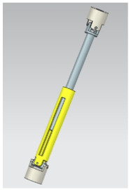
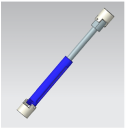
There are two different types of struts used in the OnePiece external fixator. The only difference between the struts is that one has universal joints in both ends and the other type has regular joints perpendicular to each other in the ends. The regular joint struts are placed at the ends of the external fixator, while the universal joint struts are placed in the middle next to each other.
3.4 Middle Plate
|
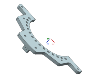
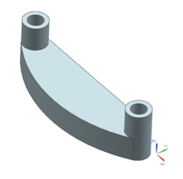
The middle plate connects with the two universal joint struts to the base of the external fixator. The universal joint struts are connected to the two parallel holes in the middle of the plate. Furthermore, this plate has also the task of holding the pin which goes to the bottom part of the broken bone. |
3.5 Bottom Plate
|
The bottom plate has the function of connecting the regular joint struts to the bottom part of the fixator. Besides, it too helps with the mobility in the “x” direction with the help of a screw. The next two pieces are not part of the main components; however, it is important to mention them to understand further explanations. |
3.6 Retainers
3.7 Screw
4. Ergonomics
As established above, OnePiece’s primary goals are to enhance the x-ray imaging and to improve the healing process for the patient to be as comfortable as possible. The first goal is automatically achieved by designing OnePiece to be half a circle; this provides a complete window opening to take better x-ray images. Nevertheless for the second goal, which is to improve the comfort of the patient throughout the curing procedure, it is essential to make an ergonomic study of how OnePiece will develop a more peaceful recovery over the Taylor Spatial Frame or another circular external fixator.
To formulate the comparison between OnePiece and circular external fixators, one must think about a normal person’s everyday activities. Consequently, for the most part of the comparison the analysis will be done by visualizing a patient using the OnePiece. However, because it is different to have the device installed in the arms and in the legs there will be several explanations for the same activity.
To formulate the comparison between OnePiece and circular external fixators, one must think about a normal person’s everyday activities. Consequently, for the most part of the comparison the analysis will be done by visualizing a patient using the OnePiece. However, because it is different to have the device installed in the arms and in the legs there will be several explanations for the same activity.
|
The main differences may be felt/seen when the patient is resting on a chair or lying on a bed. Because OnePiece is half circle, the person will have a relief when laying the leg or arm on a solid surface to rest. This provides a lot more comfort rather than having a full circle installed on a limb, which is more inconvenient. Having a full circular fixator creates an easier environment to generate unwanted stress simply because there is more area of contact.
|
The previous picture is a typical walk when a leg moves forward. A circular fixator obviously obstructs the natural movement of the leg when moving. With a circular fixator the moving leg would have to redirect in order to move forward without hitting. Moreover, the same thing would occur in the arm; with a circular fixator there would be unnatural stress immediately after an installation in the humerus or the radius bones. This is due to the natural position of the arm when resting. In any case, if the OnePiece external fixator was installed in a certain position it may be capable of reducing unnatural stress in the arm or leg when moving or resting. This is due to the design being half a circle which leaves more space for the limbs to be static or moving.
Another important part in the patient’s life during the recovery progression is the hygiene in the treated limb. The patient must clean the pin entrances with a sterilized solution using cotton applicators. It is undoubtedly easier to clean the treated limb with a half circle fixator than a full circle simply because there is more accessibility to reach the entrance of the pins.
In summary, the half a circle OnePiece external fixator is more ergonomic than any full circle external fixator such as the Taylor Spatial Frame. As described above, the mundane activities of a normal human being are performed better with a half a circle fixator frame. To conclude, it is believed that OnePiece has several advantages over its competitors; therefore it is the perfect choice to start a treatment to heal a limb bone.
5. Material Selection Process
The selection of the correct material for a design is a crucial step in the process because it is a key connection between computer/hand calculations and lines on engineering drawings for the working design. It is a complex task since there are over 100,000 engineering materials to choose from. The engineering area for materials science focuses greatly on six major classes of materials: metals, polymers, elastomers, plastics, and composites. As a designer, it is crucial to undergo a series of screening processes in order to narrowing possibilities.
In addition, it is imperative to state the great link between materials selection and design. Since improperly selecting a material will not only lead a failure of a part but also will lead to unnecessary cost. The selection of material works in conjunction with selecting an appropriate manufacturing route for an existing product or design. The following information shows some of the critical materials’ properties when it comes to approaching a proficient selection process. This criterion will be targeted to the external bone fixator portraying an overview of the most critical factors involved in its design.
Criteria for best material selection when it comes to screening process:
1. Mechanical Properties.
· Strength (Yield strength).
· Stiffness.
· Price.
· Density (light weight).
2. Wear of materials.
· Issue generated as a result of having two or more components in contact.
· Wear resistance.
· Fatigue.
· Life Cycle. N-number of cycles.
3. Corrosion.
· Environment to which device is exposed.
· Must be prepared to resist corrosion.
· Surface coating method, painting, cathodic protection (Critical methods to minimize failure modes and increase service life).
· Time & temperature dependent.
4. Ability to manufacture.
· Must be considered in order to make it a commercial product.
· Dimensions must be accurate (gear) for expected performance.
· It has to be machined in the production for accurate dimensions.
· Machining with minimum cost & still meet functionality.
5. Cost.
· Critical fact for material selection
· Competitive in the market.
· Cost can be neglected ONLY when human life & performance are top priority.
According to the American Society which studies materials science in depth states the relevant criteria with respect to manufacturing requirements, service performance for each individual part of the fixator as well as their mechanical properties.
ASTM (American Society for Testing and Materials) Criteria
Manufacturing requirements:
1) Number of parts required.
2) Size & complexity of parts.
3) Tolerance.
4) Surface finish.
5) Fabricability of material.
Service Performance:
1) Stresses.
2) Corrosion.
3) Temperature.
4) Radiation.
5) Vibration.
Mechanical Properties:
1) Yield strength.
· Tension.
· Compression.
· Shear.
2) Fatigue properties.
· Smooth.
· Notched.
· Corrosion fatigue.
· Rolling contact.
3) High-temperature behavior.
· Creep.
· Stress rupture.
4) Wear properties.
· Abrasion.
· Erosion.
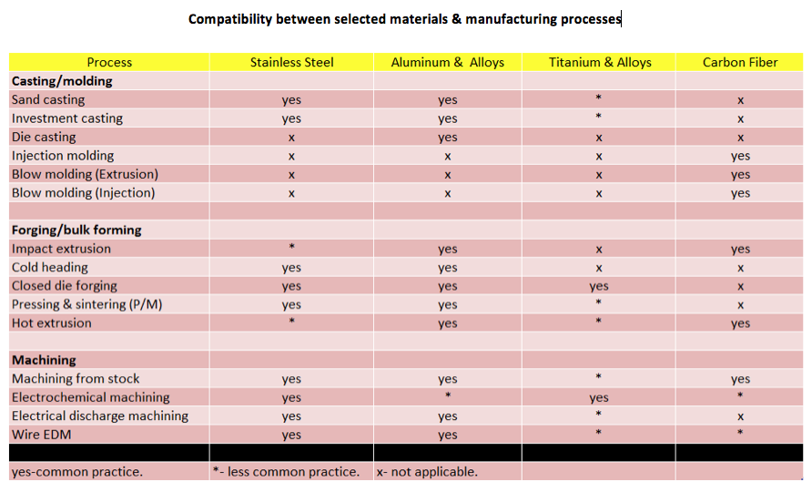
As previously stated, there is a broad range of materials to choose from and it is the responsibility of the designer to narrow those multiple possibilities. During the first stage of the screening process, proficient materials selection software was used in addition to members’ analytical thinking. CES EduPack ™ was a helpful software program in which the screening process is substantially facilitated. The software is enabled with multiple materials properties including mechanical, thermal, and electrical. It is important to mention that it has the capability to relate each material to a narrow world of possibilities for manufacturing processes called Universe Process. The screening process for materials selection was divided into several stages:
5.1 1st Stage: Screening Process
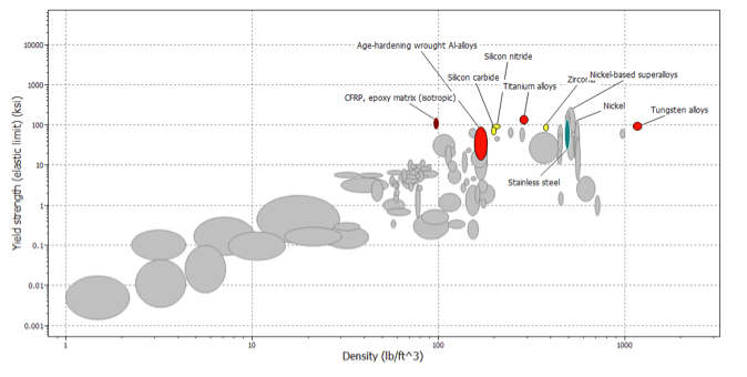
During this stage several parameters were considered critical for the external fixator to begin with. Since we wanted a strong material, which would be subjected to a certain percentage of deformation, specific yield strength was selected. A minimum limit of 88 ksi was set for the initial yield strength parameter. The basis for this parameter selection was to avoid obtaining those materials such as woods, plastics, and certain elastomers. In addition, a predetermined value was given for the density. The density considered at this stage was 99 lb/ft^3. Nonetheless, a value of 1 dollar per unit pound was given in order to resemble a low cost material. Even though, this last assumption was taken into account for materials selection it cannot be a top priority since it may jeopardize patient’s health.
The following graphical representation shows a relationship between yield strength, the ability to experience elastic deformation and be able to return to its original shape, and materials’ density, which is related to weight of the materials.
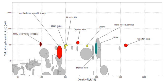
The next representation is the same as the previously mentioned but has a close-up for appreciation purposes. An extensive list was narrowed down to a group of 10 different materials.
The next representation is the same as the previously mentioned but has a close-up for appreciation purposes. An extensive list was narrowed down to a group of 10 different materials.
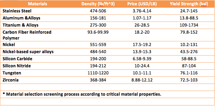
The following tabular representation portrays those materials, which were considered according to the specifications provided above. It relates each material’s given strength along with weight and price.
5.2 2nd Stage: Screening Process
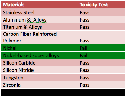
There was an on-going need to narrow down the list of materials. Since that material which is demanded by the external fixator must be ergonomically friendly and must NOT be toxic, a toxicity test was performed to evaluate each material. Those materials that are NOT toxic will approve the test. Those that fail the toxicity test have a small possibility of being considered. Some trade-offs might be possible but must pass future analysis.
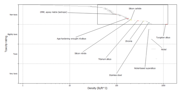
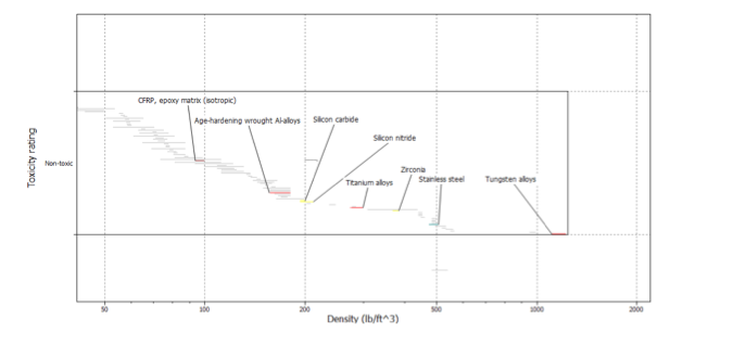
The following data collected was obtained on the basis of density compared to those toxic & non-toxic materials.
The following data collected was obtained on the basis of density compared to those toxic & non-toxic materials.
For representation purposes, we included an additional graph that focuses solely on those non-toxic materials. Identical graph. Zoom was increased.
After performing the toxicity test, two out of ten materials were no longer to be considered. Nickel as well as its composites is toxic. It could be highly risky to continue considering nickel for future applications. This examination and analysis reduced the number of materials down to 8 materials.
5.3 3rd Stage: Screening Process
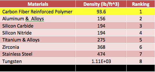
There is a broad range for density parameters for each of the 8 materials. For practical purposes, the lowest density was considered when it came to performing a ranking of materials 1-being the top material or lightest and 8-being the heaviest material.
Initial Ranking:
Initial Ranking:
After this analysis was concluded, our results indicate that CFRP is the lightest material among the 8 considered. Tungsten is the heaviest.
Intermediate Ranking-
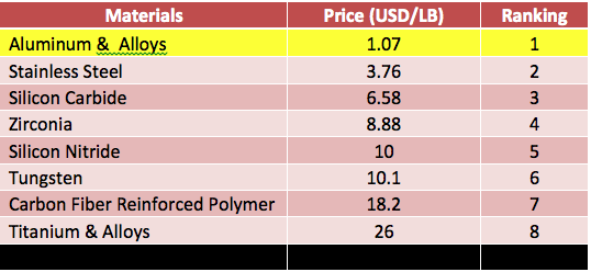
A critical parameter for materials consideration is materials’ cost. In addition, manufacturing cost and operational cost need to be considered. The last one, its beyond our scope.
Intermediate Ranking-
A critical parameter for materials consideration is materials’ cost. In addition, manufacturing cost and operational cost need to be considered. The last one, its beyond our scope.
Aluminum & aluminum alloys were considered to be the cheapest monetarily speaking. Titanium & titanium alloys being the most costly. A trade-off could be undertaken at this stage since titanium properties indicate that it is relatively & strong.
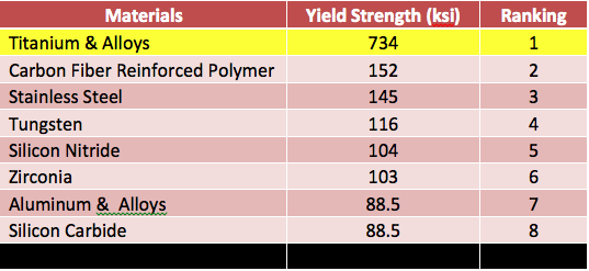
Post-intermediate Ranking-
Post-intermediate Ranking-
At this point, titanium possesses the highest yield strength. Followed by CFRP and stainless steel. They have the highest capability of experiencing deformation under the elastic region by a certain percentage and still be able to return to their normal shape.
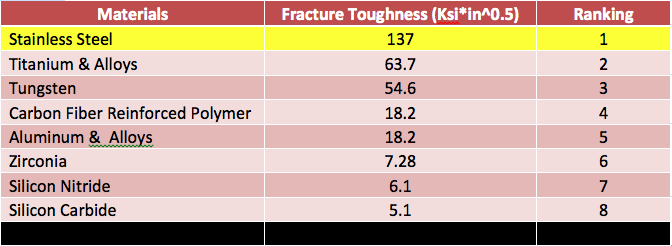
Ranking-based on fracture toughness.
This analysis process deals with the ability a certain material has, to absorb a given amount of energy as well as experience a certain percentage of deformation before fracture. The highest the fracture toughness, the more amount of energy absorbed before experiencing fracture.
“The requirement for fracture toughness of the material is used to eliminate any possible ceramics in our list.”
At this point of materials selection, stainless steel defeats titanium as it absorbs more energy before fracture.
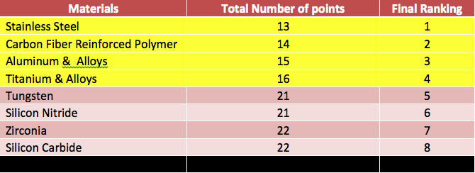
Final Ranking-Screening Process.
Before drawing conclusions about what materials are more appropriate for our particular design, each of the tests performed have a ranking score. In addition, during this stage we added all the possible points for each and every material. Since the lowest value indicates the most relevant material for our design, that particular material, which accumulates the least number of points, will be paid closer attention to. So the lower the value of the ranking parameter, the better the material.
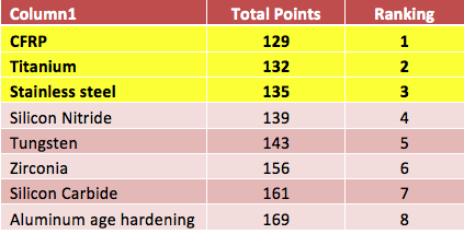
The top 4 materials were selected according to our final ranking. Since only three critical factors were used for our screening process, it is not safe to conclude our selection materials process. A second test is to be performed using solely mechanical properties. The top candidates will be compared with the ones obtained previously.
6. Market Analysis
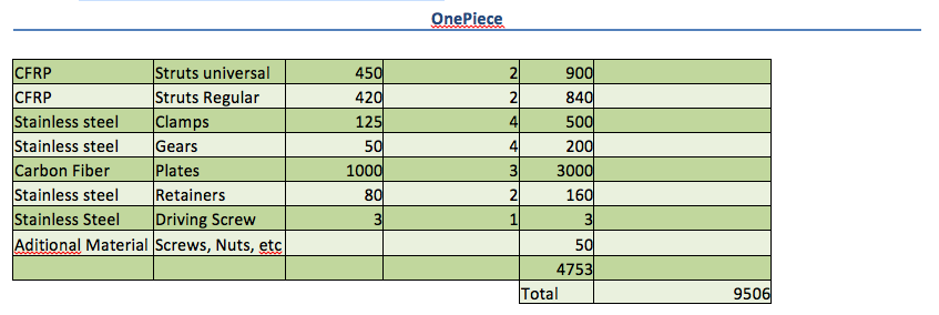
The market analysis performed in this report was a rough estimate of what the team believes the prices would be for the Taylor Spatial Frame and the OnePiece fixator components. In the case of the TSF the price should be around $ 10,000 because of what Dr. Amr told the team. Nevertheless, because the machining prices are unknown, these costs were calculated with the help of a Machining Cost Estimator online. This webpage and other research done was what determined the values typed into the excel file. Furthermore, a profit of 100% was assumed in order to get the highest price possible. The following table presents the analysis:
The following table has the price for the TSf
The following table has the price for the TSf
The next table contains the prices for OnePiece
7. Finite Element Analysis
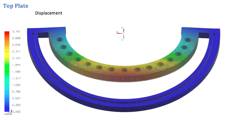
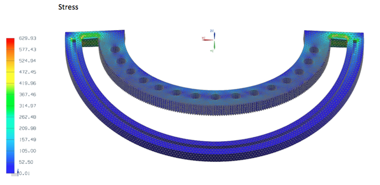
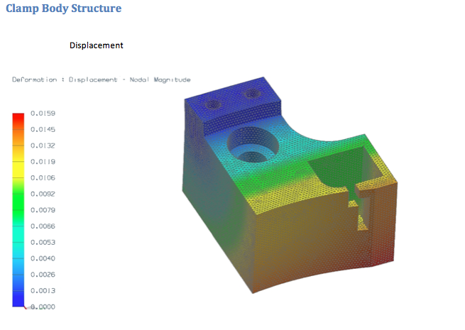
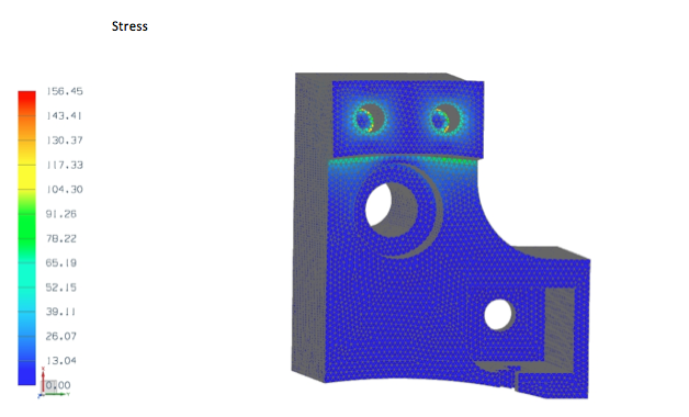
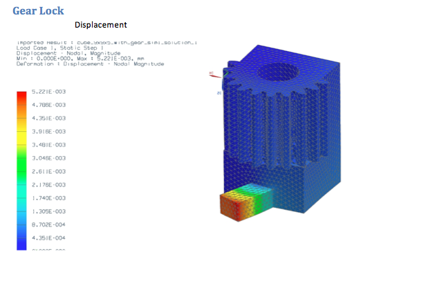
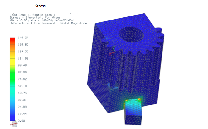
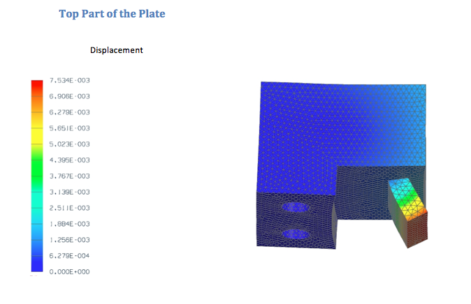
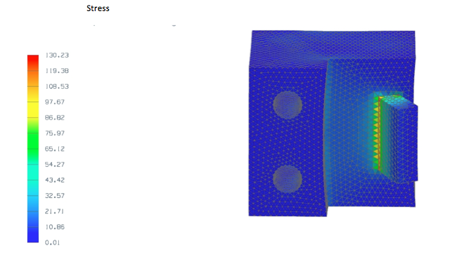
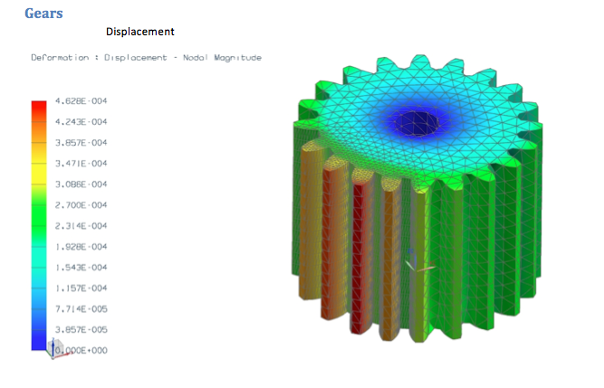
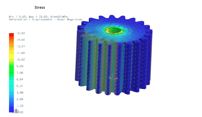
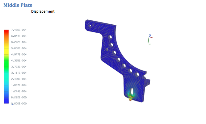
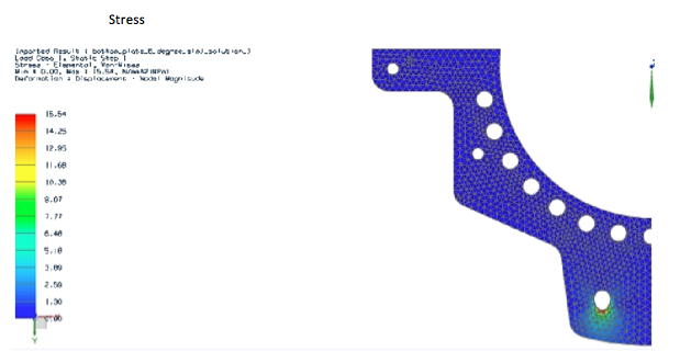
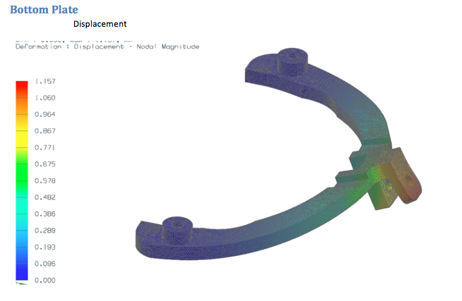
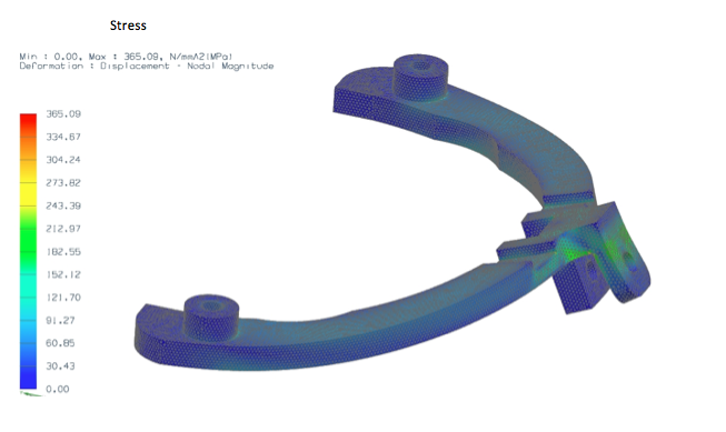
Before starting the Finite Element Analysis description it is important to state that the materials used to perform the FEA examination were taken from the first places of the charts above. Now, since some components are more crucial than others, stronger materials were selected in order for these pieces to endure the stresses and cycles. The material used for each of the components selected will be described along with the FEA.
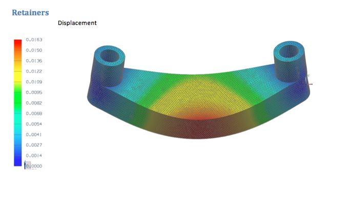
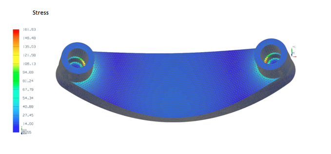
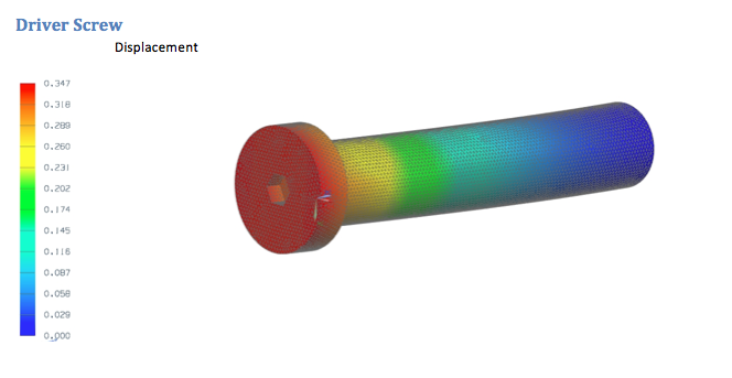
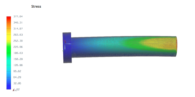
An additional essential limitation also needs to be explained before revealing the FEAs. The materials selected for the prototype are cheaper than the ones selected to generate the FEAs. This is due to the budget and technology at hand in order to build a physical prototype. Most of the prototyping materials are aluminum alloys among other metals. On the other hand, the materials selected to perform FEA are the best selections from the Material Selection process. However, the FEA were performed in the most critical components. The analysis was performed assuming a hundred kilogram person. In any case, there are two FEA in each piece, when the person steps in the fixator, and when the leg is lifted from the ground to move forward. Because of length purposes, only the maximum loads and the stress and displacement analysis will be presented in this part of the report, everything else will be added in an appendix at the end of the report. The following are the selected components with the Finite Element Analysis.
*Note: The units for displacement are in mm. The units for stress are in MPA
The clamps were separated into its smaller components to check each individually in order to reduce the error in the Finite Element Analysis
For the middle plate analysis, the piece was cut in half in order to increase the quality of the mesh. However, the necessary calculations were obtained to make a correct analysis in the half of the piece.
8. Fatigue Analysis
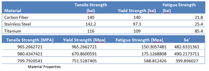
After completing the FEA lots of information were found about the components of OnePiece. Because of this, a fatigue analysis is practical to perform at this point. As stated above, the materials chosen to build the components of OnePiece are Carbon fiber, Stainless Steel and Titanium. The fatigue analysis was conducted in the critical pieces as well as the FEA. The fatigue analysis was generated in excel in order to perform exact and readable results
The following table contains the Ka factors.
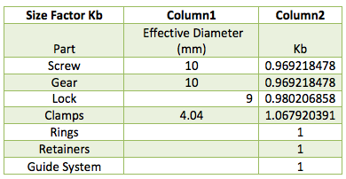
The next table contains the Kb factors
The following table contains the Kc factors for the components the only different one is for the screw which is in column three
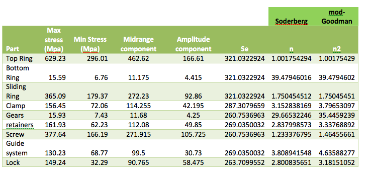
The final table contains the fatigue analysis and it is pretty self explanatory
9. Functionality
To explain the functionality of OnePiece it is important to remember the first coordinate system established above. The movement references are explained following the mentioned coordinate system. However, there are six degrees of freedom which have to be accomplished and it is easier to explain them piece by piece. Furthermore, there are several component capabilities that help OnePiece to stay stable which are also part of the functionality. The rundown for the explanation will be from top to bottom starting with the degrees of freedom and later on the stability mechanisms.
It is important to explain that the six degrees of freedom which OnePiece provides are relative to each of the plates. In odder words, there is no need to have six degrees of freedom in the top plate and six on the bottom plate. OnePiece has one degree of freedom in the top plate, four in the strut movement and the last one in the bottom plate. Together they all complement each other and sum up to six dof.
Rotation in “Z”
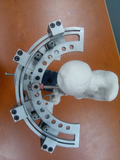
The rotation in the “z” axis is accomplished with the help of the gear system in the top plate of OnePiece. The clamps contain a lock system along with the gear which prevents the top plate from rotating freely. In order to be able to twist the top plate the four lock systems located in each clamp need to be pushed down and restrained with a butterfly nut. Once this is done, the rotation is performed by putting an Allen key in one of the gears in manually twist the gear which will make the top plate move in the desired angular direction. After the destination is reached the lock systems are reestablished and the plate is restrained one again.
Linear movement in “Y” & “Z” and rotation in “X” and “Y”
The movements stated above are performed by adjusting the length of the four struts. The linear movement in “Y” is performed by first lengthening or reducing the two regular joint struts to the same length. The second step is to lengthen a universal strut and reducing the other one in the measure desired in order to reach the destination.
The linear movement in “z” is performed by simply lengthening or reducing all of the struts at the same extent until the destination is reached.
The rotation in the “x” direction is carried out by decreasing the length of one universal joint strut and one regular joint strut of the same side, while doing the exact opposite with the other side until the destination desired is reached.
The rotation in the “y” direction is done by decreasing the length of the two universal joint struts and lengthening the regular joint struts. To rotate in the opposite direction the exact opposite of the first rotation movement should be done.
Linear Movement in the “X” direction
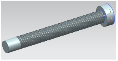
The linear movement in the “x” direction is completed with the help of the driver screw in the bottom plate. This screw performs the movement with the help of two nuts which move the bottom plate through the middle plate.
It is important to express that these adjustments are done little by little through a large period of time. After the initial installation the healing process lasts between 6 and 10 months to finish treatment. However, the movements are done in the fashion explained above each time until the final destination is reached. In summary, the functionality of OnePiece will ultimately reach the goal of healing the bone by aligning it as perfectly as possible.
10. Conclusions and Final Product
The primary purpose for undertaking this design project was to deal with the problems that are usually encountered with the Taylor Special Frame. Such direction was aimed at improving the patients’ comfort as well as improving x-ray imaging. Nevertheless, external fixator stability remained as one of the top priorities. The team addressed the issue of x-ray medical interpretation by reducing body frame to half its original frame. This was accomplished by using carbon fiber reinforced polymer. Its yield strength is as high as its tensile strength, making it a strong material for this application. Also, one of its features is that it is radio-translucent. Such last feature was the determining factor for choosing this material as opposed to titanium, which has similar strength capabilities.
In order to account for stiffness and stability of fixator, regular pins were used on both extremities as opposed to TSF using solely universal joints. In addition, ergonomics on the device was also a top priority. This issue was addressed by reducing the intermediate and bottom plates’ bulkiness. Such accomplishment makes it easier for patients’ comfort and improves on regular resting positions of the human body.
Once the device is installed onto the human body or limb under treatment, it is easier for patient to perform daily activities. Nonetheless, it is extremely important to state that even though patients’ comfort was improved, orthopedist handling was not. The varied use of clamps operated with a simple gear system triggers doctors’ ease to make correction adjustments. Our prototype will continue to operate under the TSF functionality and be able to treat mal-functions, non-junctions, breakage as well as lengthening of limbs in the human body. It is important to specify that this analysis and procedure will be based depending on users’ needs and directed depending on the bone under treatment. Cross sectional area, size, weight, volume, mechanical properties will change depending on application and material used.
